Detection device

Active Publication Date: 2012-11-01
SEIKO EPSON CORP
View PDF5 Cites 19 Cited by
  • Summary
  • Abstract
  • Description
  • Claims
  • Application Information

AI Technical Summary

Benefits of technology

[0029]According to this configuration, the sensor chip is thus cleaned up in the second mode performed prior to the first mode. Thus, the detection accuracy of the detection device can be improved. Further, due to the second mode p

Problems solved by technology

However, according to the detection device described above, although it is possible to detect whether or not the sample molecules a

Method used


Image

  • Detection device
  • Detection device
  • Detection device

Examples


embodiment

1. Basic Configuration of Detection Device

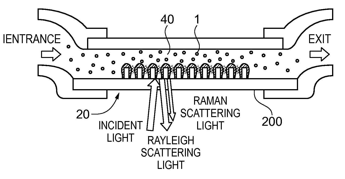
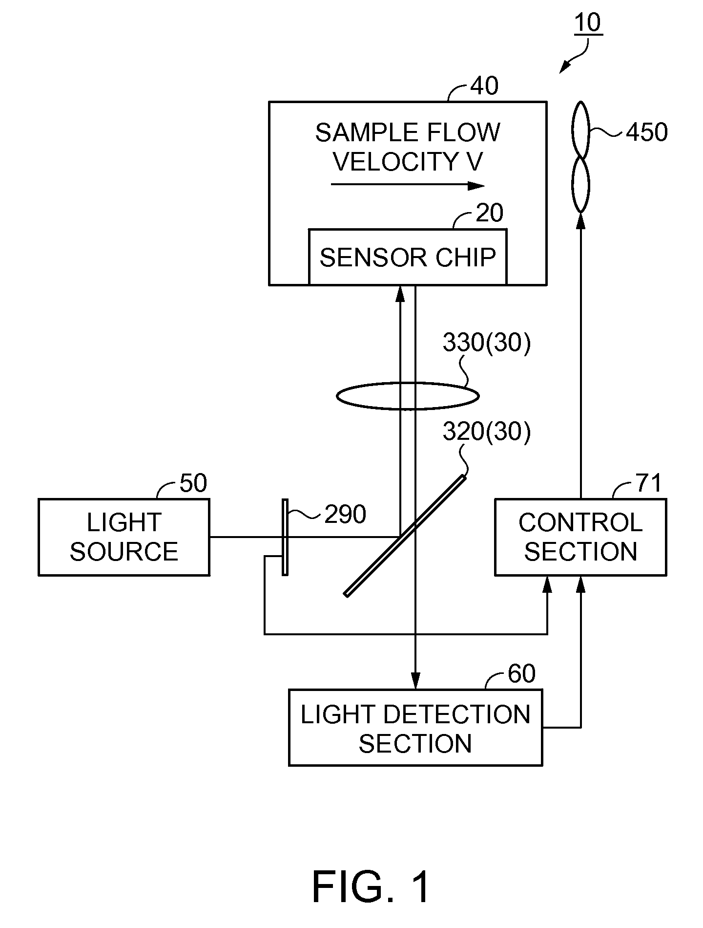
[0050]FIG. 1 is a block diagram showing a configuration of the detection device according to the present embodiment. As shown in FIG. 1, the detection device 10 has a sensor chip (an optical device) 20, a suction section 40, a light source 50, a light detection section 60, a control section 71, and a light intensity adjustment section 290. Between the sensor chip 20 and the light source 50, and between the sensor chip 20 and the light detection section 60, there is disposed an optical system 30. In the present embodiment, the fluid sample is, for example, air, and the inspection target material can be set to specific gas molecules (sample molecules) in the air, but is not limited thereto.

[0051]The suction section 40 is provided with a negative pressure generation section, for example, a fan 450, and sucks the fluid sample. The negative pressure generation section is not limited to the fan, but is only required to be what can generate a negat...

modified examples

5. Modified Example Using Reference Molecules In Combination

[0086]Then, one modified example of the detection device as an embodiment of the invention will be explained with reference to FIGS. 13 through 18. The present modified example is different from the embodiment described above in the point that a reference molecule storage chamber is provided. It should be noted that the explanation on the point the same as in the embodiment described above will be omitted.

5.1. Overall Structure

[0087]It is assumed that TNT molecules as component molecules of an explosive are detected as the inspection target material in, for example, a port or a harbor. In normal cases, the TNT molecules do not exist in the air. Therefore, if the detection along the method of the embodiment described above taking the TNT molecules as the sample molecules, it takes eternity to end the first mode (the adsorption mode). This is because there is high probability that in normal cases the SERS intensity of the TNT...

second experimental example

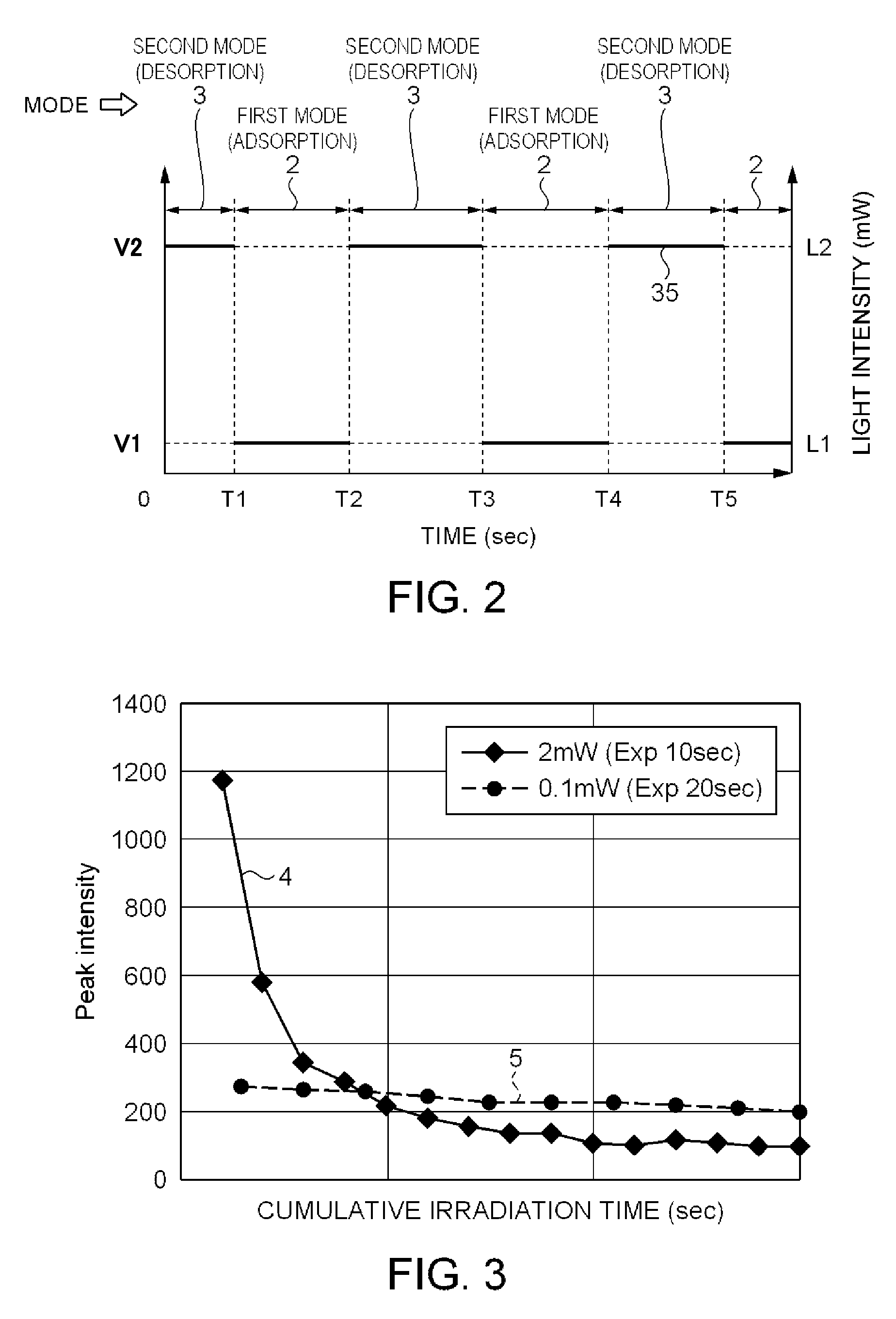
5.2. Second Experimental Example

[0094]FIG. 17 is a graph for explaining the first mode and the second mode. As shown in FIG. 17, an experiment has been conducted along the switching lines 25 of performing the first mode 2 (the adsorption mode) and the second mode 3 (the desorption mode) alternately. It should be noted that the sample molecules 1 as the inspection target material are not particularly assumed in the second experimental example. As the light source 50, a He—Ne laser with the excitation wavelength of 632.8 nm, and the intensity of 2 mW is used. As the material of the sensor chip 20, Ag is adopted. In the first mode 2 (the adsorption mode), the fluid transport rate W1 of the fan 450 is set to 20 ml / min, the excitation light intensity L1 is set to 0.1 mW on the sensor chip 20, and the measurement exposure time in the light detection section 60 is set to 20 seconds. In the second mode 3 (the desorption mode), the fluid transport rate W2 of the fan 450 is set to 200 ml / min,...


PUM


Abstract

A detection device includes a sensor chip, a suction section adapted to suck a fluid sample to the sensor chip, a light source adapted to irradiate the sensor chip, a light intensity adjustment section adapted to adjust intensity of the light, a light detection section adapted to detect the light reflecting the sample adsorbed to the sensor chip, and a control section adapted to perform drive control on the suction section. The control section sets the suction flow velocity to V1 in the first mode in which the light detection section performs the detection, and sets the suction flow velocity to V2 (V2>V1) in the second mode. The light intensity adjustment section sets the light intensity to L1 in the first mode, and sets the light intensity to L2 (L2>L1) in the second mode. The first and second modes are switched based on the signal from the light detection section.

Description

BACKGROUND[0001]1. Technical Field[0002]The present invention relates to a detection device.[0003]2. Related Art[0004]In recent years, as one of sensitive spectroscopic techniques for detecting low-density sample molecules, surface enhanced Raman scattering (SERS) spectroscopy using surface plasmon resonance (SPR), in particular localized surface plasmon resonance (LSPR), has been attracting attention (Japanese Patent No. 3714671, JP-A-2000-356587). The SERS denotes a phenomenon that the Raman scattering light is enhanced 102 through 1014 times on a metal surface having a structure of providing unevenness in nanometer scale. The sample molecules are irradiated with an excitation light with a single wavelength such as a laser. The light with a scattering wavelength (the Raman scattering light) slightly shifted from the wavelength of the excitation light as much as the molecular vibration energy of the sample molecules is spectroscopically detected to thereby obtain the fingerprint sp...

Claims


Application Information

Patent Timeline
IPC IPC(8): G01J3/44G01N21/55G01N21/65
CPCG01N21/05G01N2021/0346G01N2021/058G01N21/658Y10T137/0324
Inventor YAMADA, KOHEIHANO, YOSHIFUMI
Owner SEIKO EPSON CORP
Why Eureka
Try Eureka