Sterilization System And Method With Compression and Expansion

a technology of sterilization system and expansion chamber, applied in the direction of disinfection, water installation, construction, etc., can solve the problem of condensation on surfaces including the inside of the lumen

Active Publication Date: 2012-11-01
STERILUCENT
View PDF7 Cites 8 Cited by
  • Summary
  • Abstract
  • Description
  • Claims
  • Application Information

AI Technical Summary

Benefits of technology

[0016]The volume variation induces pressure variations that can be beneficial in at least five ways. First, as the boundary moves to expand the volume of the sterilization chamber, degraded hydrogen peroxide is removed from the interior of the lumen device. Second, as the boundary moves to contract the volume in the sterilization chamber, the higher concentration of hydrogen peroxide vapor outside the lumen device is forced into the lumen. Third, by controlling the rate of expansion and contraction, it is possible to control the type of flow (laminar or turbulent) within the lumen. Laminar flow in a tube has a parabolic velocity profile in the radial direction, while turbulent flow is much more uniform in the radial direction. This difference may be exploited to preferentially move non-degra

Problems solved by technology

Second, as the boundary moves to contract the volume in the sterilization chamber, the higher concentration of hydrogen peroxide vapor outside the lumen device is forced into the lumen.
Fourth, by injecting hydrogen peroxide into the c

Method used


Image

  • Sterilization System And Method With Compression and Expansion
  • Sterilization System And Method With Compression and Expansion
  • Sterilization System And Method With Compression and Expansion

Examples


second embodiment

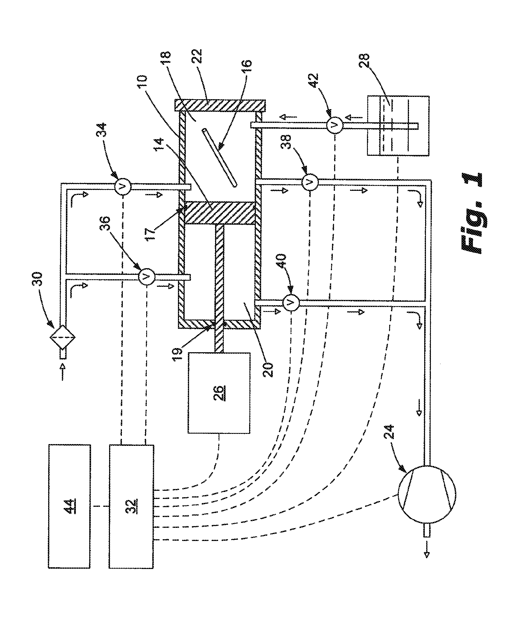
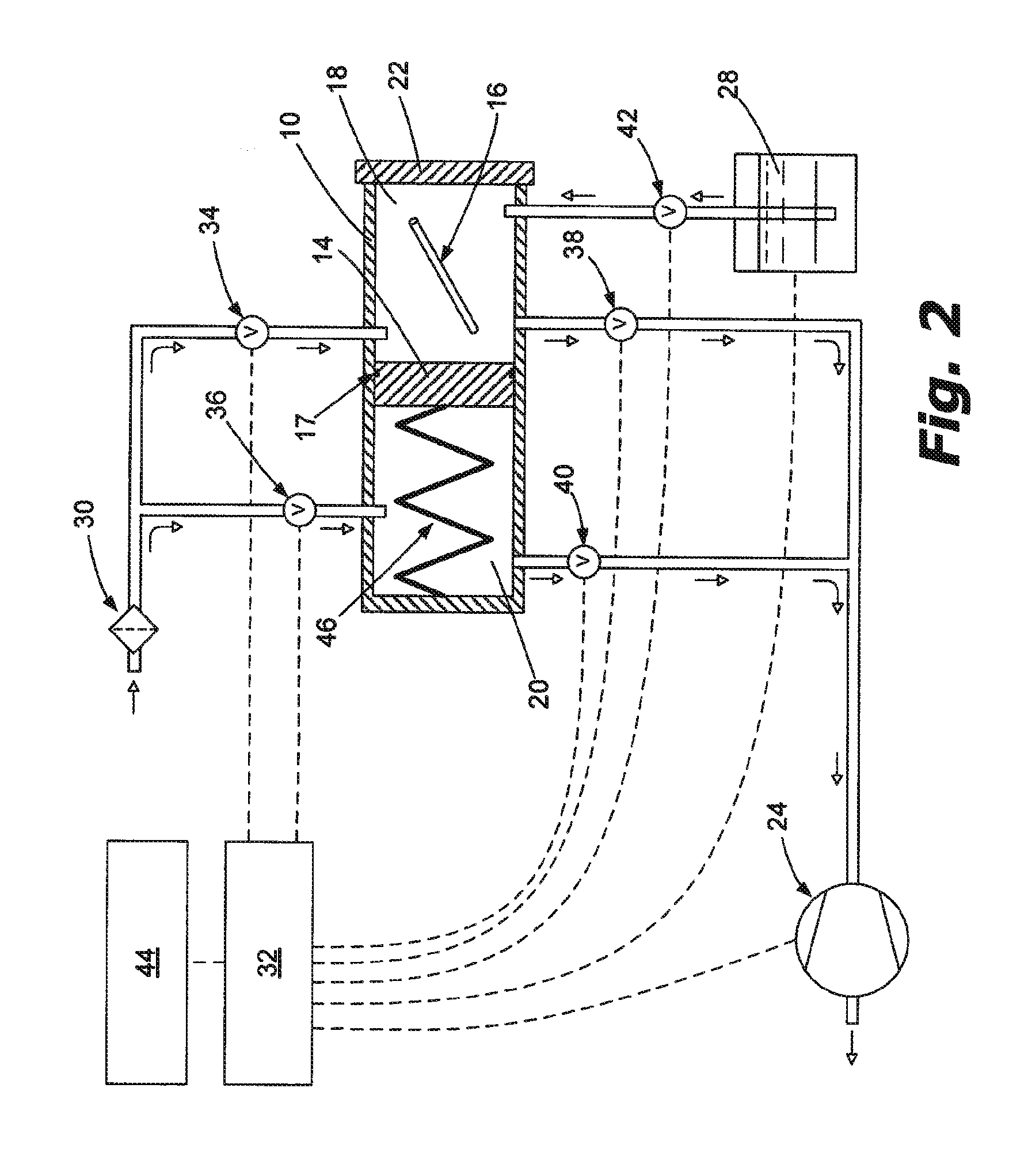
[0040]FIG. 2 is a schematic diagram of a variable volume sterilizer system. In this embodiment, as in the embodiment shown in FIG. 1, the sterilization chamber 10 is divided into two portions: a first area 18 in which item(s) to be sterilized 16 are placed and into which sterilant is admitted; and the second area 20. Area 18 and area 20 are separated by a movable boundary 14 that is sealed with respect to the chamber walls, but slidable such that the relative sizes of chamber areas 18 and 20 can be altered as part of the sterilization process via controlled movement of the movable boundary 14. More specifically, the first area 18 and second area 20 are separated by the movable boundary 14, so that when the second volume 20 is increased, the first volume 18 consequently decreases, and vice versa. One advantage of using a second area 20 within the sterilization chamber 10 is that this area may also be evacuated. When the second area 20 is at a pressure near to that of the first area 1...

third embodiment

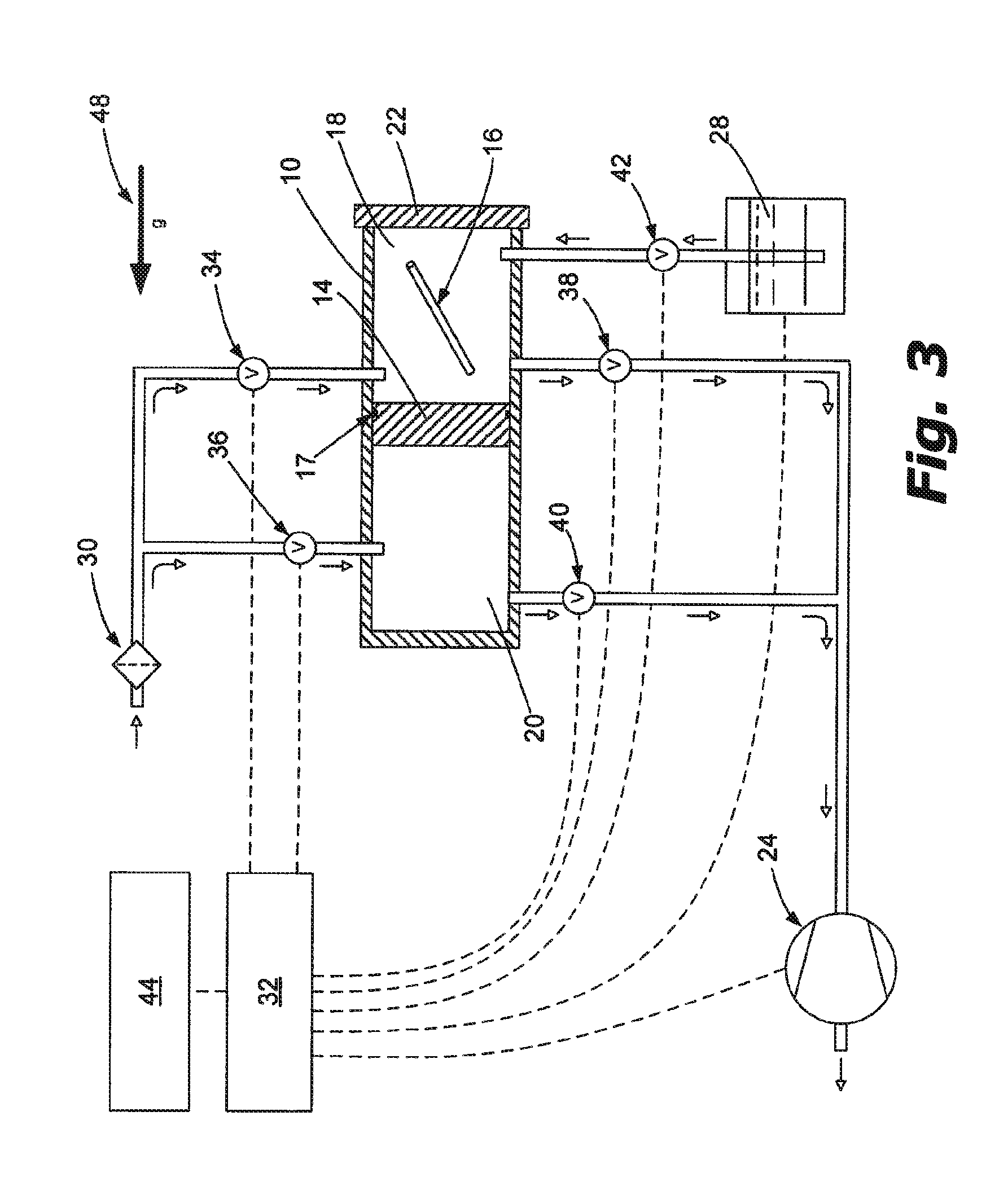
[0043]FIG. 3 is a schematic diagram of a variable volume sterilizer system similar to the embodiment of FIG. 2. In this embodiment, the spring 46 has been removed and the movable boundary 14 is moved by using the controlled actuation of inlet valve 36 and / or the outlet valve 40. Any pressure differential between areas 18 and 20 will cause the movable boundary 14 to move. When the pressure in area 20 is lower than the pressure in area 18, the boundary will move to reduce the volume of area 20 and expand the volume of area 18 in an effort to equalize the pressures of the two areas. Likewise, when the pressure in area 20 is greater than the pressure in area 18, the movable boundary 14 will move in the opposite direction. Arrow 48 in FIG. 3 is present to suggest that gravity can also be employed to expand the size of area 18 except when the pressure in area 20 is sufficiently higher than the pressure in area 18 to resist the force of gravity.

fourth embodiment

[0044]FIG. 4 is a schematic diagram of a variable volume sterilizer system. In this embodiment valves 36 and 40 of the previously described embodiments have been eliminated such that actuator 26 exclusively controls the position of the movable boundary 14.


PUM


Abstract

An apparatus and method for achieving low temperature vapor sterilization of objects which may involve objects having a lumen. Following evacuation of the sterilization chamber and the introduction of a vaporous or gaseous sterilant, the volume of the chamber is changed by actuation of a movable boundary in the chamber to increase and decrease the pressure in the chamber thus driving the sterilant into and out of such lumens.

Description

CROSS REFERENCE TO RELATED APPLICATION[0001]This application is a non-provisional application for Application No. 61 / 479,422, filed Apr. 27, 2011 and claims priority from that application which is also deemed incorporated by reference in its entirety in this application.BACKGROUND OF THE INVENTION[0002]I. Field of the Invention[0003]The present invention relates to sterilization and disinfection systems that utilize gas or vapor phase sterilants or disinfectants and, more particularly, to low-temperature, hydrogen peroxide vapor sterilization systems.[0004]II . Related Art[0005]Low temperature application of hydrogen peroxide vapor is highly effective when sterilizing objects having relatively open and accessible surfaces such that the hydrogen peroxide vapor can easily surround and contact all surfaces of the object and sterilize these surfaces. To date, low temperature application of hydrogen peroxide vapor has proven to be more difficult when sterilizing objects having diffusion ...

Claims


Application Information

Patent Timeline
IPC IPC(8): A61L2/16
CPCA61L2202/122A61L2/208
Inventor OLSON, STEVEN J.
Owner STERILUCENT
Why Eureka
Try Eureka