Device and method for expressing human breast milk

a technology for expressing breast milk and breast milk, which is applied in the direction of machines/engines, mechanical devices, dressings, etc., can solve the problems of restricting the performance of the device, requiring a relative large volume of the milk collecting container to be evacuated, etc., and achieves the effect of increasing stability, and facilitating the insertion of the connector

Active Publication Date: 2012-11-01
MEDELA HLDG AG
View PDF6 Cites 38 Cited by
  • Summary
  • Abstract
  • Description
  • Claims
  • Application Information

AI Technical Summary

Benefits of technology

[0014]Since the entire system is flooded by milk and there is therefore no longer a vacuum line in the classic sense, a lower pumping power is required in order to express breast milk. Typical values for air output are up to 500 ml / min and for milk output up to 100 ml / min. The vacuum pump can therefore be configured to be smaller and lighter, so as to be less conspicuous to onlookers. The mother can use the vacuum pump more discreetly. In addition, due to the lower pumping power requirement, the vacuum pump is quieter during use, which in turn increases the comfort and discretion.
[0047]The combination of the three elements a vacuum-transmitting and milk-conducting line, a pump chamber diaphragm with its triple function, and the breast shield that is of small design and avoids dead volumes results in a device that can be designed to be small and quiet, and furthermore is optimally suitable for any type of use, in particular “hands-free” use.

Problems solved by technology

The device has the disadvantage that the relatively large volume of the milk collecting container likewise has to be evacuated.
The “dead volume” considerably restricts the performance of the device.

Method used


Image

  • Device and method for expressing human breast milk
  • Device and method for expressing human breast milk
  • Device and method for expressing human breast milk

Examples


Embodiment Construction

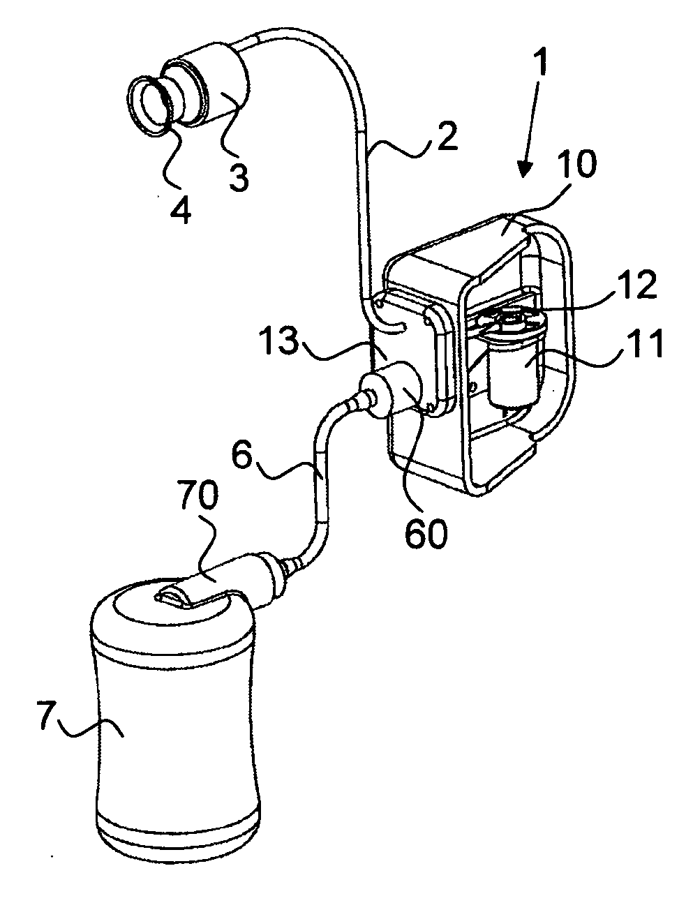
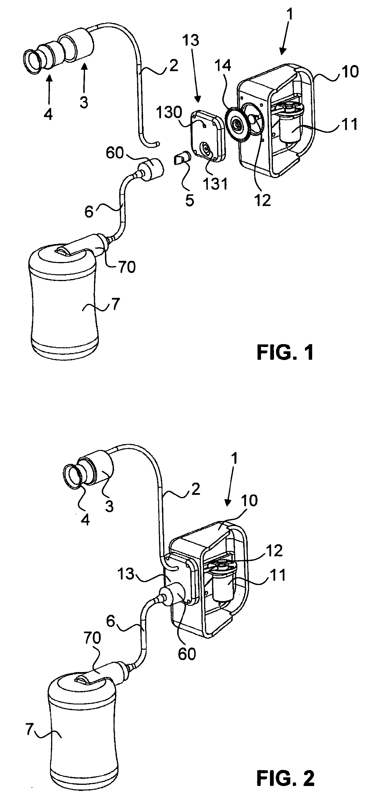
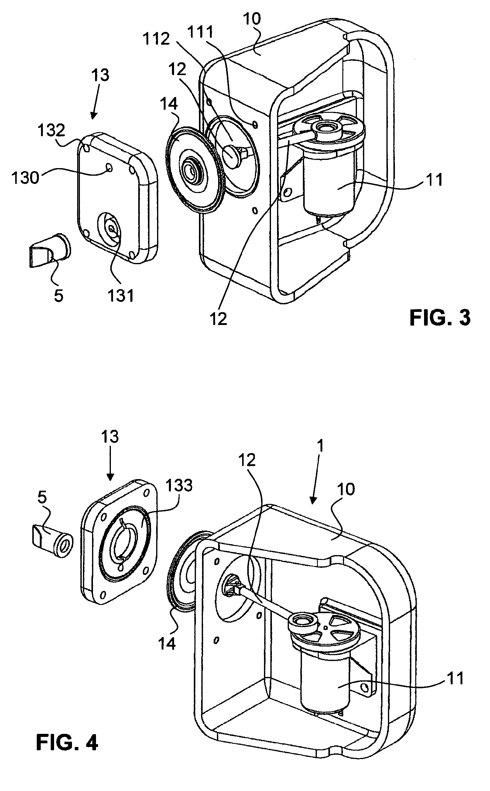
[0067]FIGS. 1 to 5 illustrate a first embodiment of the device according to the invention. The device has a vacuum pump 1, a first line 2, a coupling part 3, a breast shield 4, a nonreturn valve 5, a second line 6, and a milk collecting container 7.

[0068]The breast shield 4 is connected to the vacuum pump 1 via the coupling part 3 and the first flexible line 2. The second flexible line 6 leads from the vacuum pump 1 to the milk collecting container 7, the connection being provided with the nonreturn valve 5. The two flexible lines 2, 6 are preferably tubes, preferably made of silicone.

[0069]As illustrated in FIG. 6, the milk collecting container 7 may alternatively be fastened directly to the vacuum pump 1. For this purpose, there is preferably a suitably shaped adapter 70 on the milk collecting container 7, the adapter being detachably connectable to a housing 10 of the vacuum pump.

[0070]The vacuum pump 1 has the abovementioned housing 10, a side wall of the housing 10 not being il...


PUM


Abstract

A device for expressing human breast milk has a breast shield for bearing against a mother's breast, a vacuum pump for generating a vacuum, a line which connects the vacuum pump to the breast shield and is intended for transmitting the vacuum generated to the breast shield, and a chamber. The line ends on the pump side in a first port of the chamber. The chamber has a second port for connection to a milk collecting container. The two ports in the chamber are connected to each other in terms of fluid communication. During the expressing operation, the line forms a milk line for transporting breast milk expressed in the breast shield to the chamber and from the chamber to the milk collecting container. The pump can be designed to be quiet and small.

Description

CROSS REFERENCE TO RELATED APPLICATIONS[0001]The present application is a U.S. National Phase Application pursuant to 35 U.S.C. §371 of International Application No. PCT / CH2010 / 000225 filed Sep. 17, 2010, which claims priority to U.S. Provisional Patent Application No. 61 / 244,636 filed on Sep. 22, 2009. The entire disclosure contents of these applications are herewith incorporated by reference into the present application.TECHNICAL FIELD[0002]The present invention relates to a device for expressing human breast milk, a vacuum pump and to a method for operating a device for expressing human breast milk.BACKGROUND[0003]Devices for expressing human breast milk are well known. In principle, there are two different types: the first device type is operated manually, i.e. the negative pressure required for the expressing operation is generated by manual actuation of the vacuum pump. In the devices of the second type, the vacuum pump is operated electrically, it being possible for the vacuu...

Claims


Application Information

Patent Timeline
Patent Type & Authority Applications(United States)
IPC IPC(8): A61M1/06
CPCA61M1/06A61M1/066A61M1/064A61M1/0072A61M1/82A61M1/067A61M1/0697A61M1/06935A61J13/00A41C3/065A61F13/00038F02M61/08A61M2202/0014
Inventor WEBER, BEDAFURRER, ETIENNESCHLIENGER, ANDRESILVER, BRIAN H.WACKERLIN, DANIELAFELBER, ARMIN
Owner MEDELA HLDG AG
Why Eureka
Try Eureka