Mixed flow type atomizing propulsion aeration cooling tower

A ventilation cooling, mixed-flow technology, applied in water shower coolers, direct contact heat exchangers, heat exchanger types, etc. Improvement and other problems to achieve the effect of optimizing the cooling effect, increasing the air volume, and reducing the resistance of the air duct

Inactive Publication Date: 2008-10-22
魏仕英
View PDF2 Cites 10 Cited by
  • Summary
  • Abstract
  • Description
  • Claims
  • Application Information

AI Technical Summary

Problems solved by technology

② Huge wind resistance exists in packing, water curtain and water mist flow
[0018] Chinese invention patent application 'downspray spray propulsion ventilation cooling tower and jet cooling fan' (200710050740.6), on the basis of summarizing the practice of spray propulsion ventilation cooling towers, proposed a design to reduce the wind pressure of the fan and increase the air volume by means of downstream spraying concept, but the design concept of increasing the air temperature has not been proposed, and the water distribution and air guidance in the cooling tower are not perfect, and there are no measures to treat the water quality and reduce the blockage

Method used


Image

  • Mixed flow type atomizing propulsion aeration cooling tower
  • Mixed flow type atomizing propulsion aeration cooling tower
  • Mixed flow type atomizing propulsion aeration cooling tower

Examples


Embodiment 1

[0040] Example 1: see Figure 1 to Figure 5

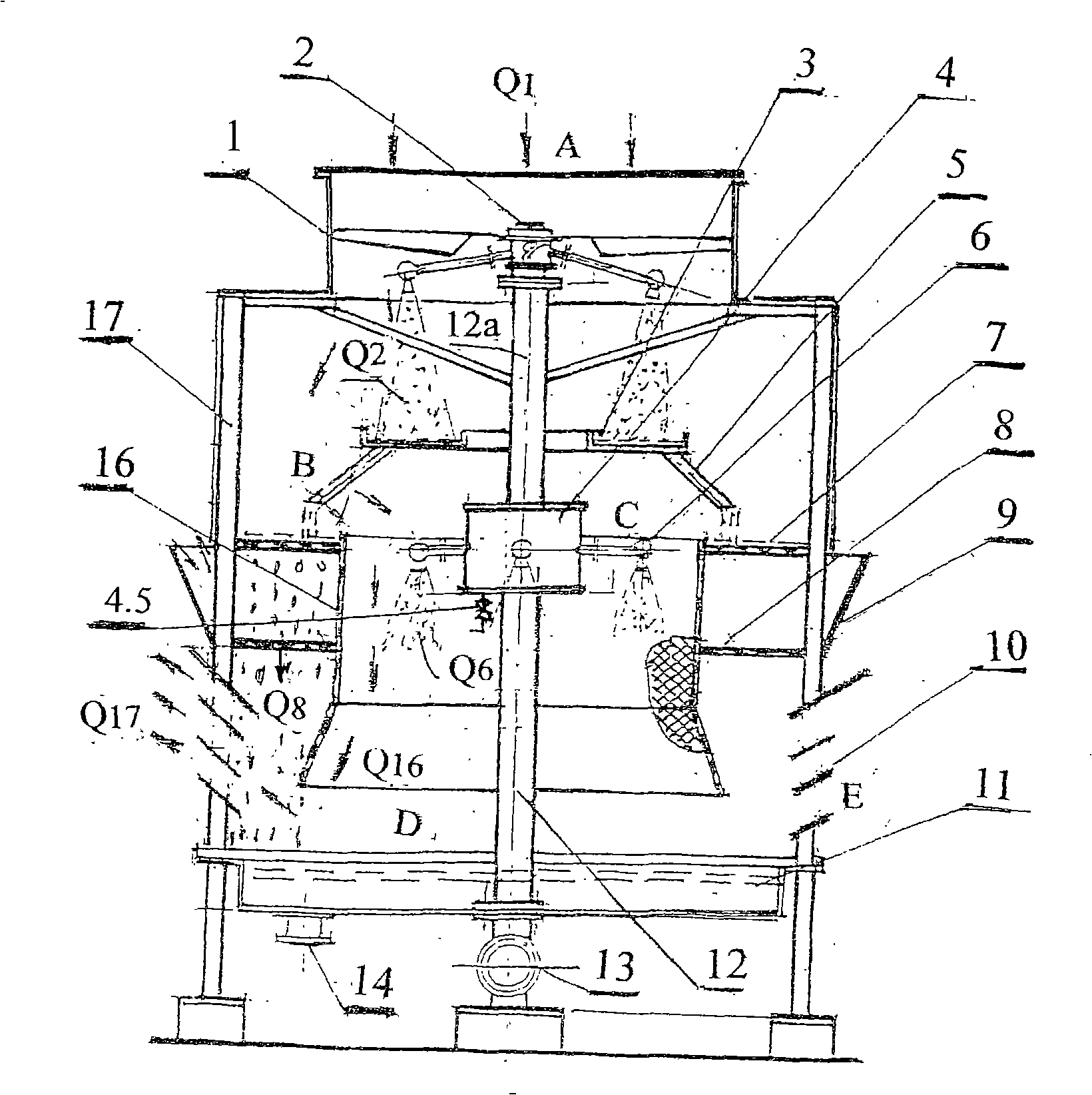
[0041] See figure 1 , mixed-flow spray propulsion ventilation cooling tower, the overall structure and layout are described as follows (A) (B) (C) (D) (E):

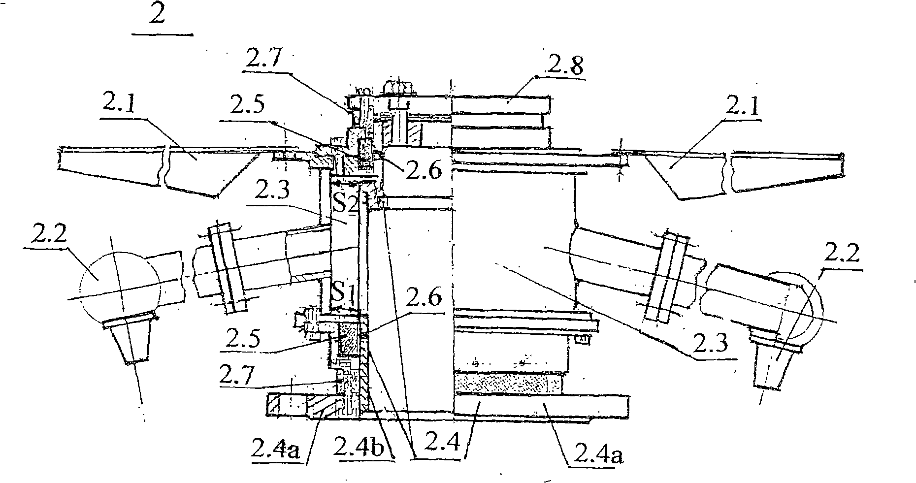
[0042] (A) In the tower body 17, the spray propulsion atomization device 2, the jet flow collecting tray 3 and three water pipes 5 and the screen air cylinder 16 fixed by its chassis are installed sequentially from top to bottom. On the outer periphery of the screen air duct 16, a water-spraying sieve plate 7 sealed between the water pipe 5 and the tower wall is installed under the water-draining sieve plate 7, and a layer of water-spraying screen that is sealed with the screen air duct 16 and the tower wall is arranged under the water-draining sieve plate 7. 8; the louver air outlet 10 is opened on the tower wall at the bottom of the water spraying screen 8 and the outer periphery of the screen air duct 16. The lower end of the water spraying screen 8 axially extends to t...


PUM


Abstract

The invention discloses a mixed flow type spraying propulsion air cooling tower. The inside of the tower is provided with a spraying propulsion atomization plant, a jet current catch pan, a water pipe and a screen stencil drogues from top to bottom; the screen stencil drogues is outside provided with a watering sieve plate and a watering screen stencil; the end of the inflow pipe is provided with a solid-liquid separator for separating the impurities, and the top thereof is provided with a swirl nozzle. The atomization plant is inner provided with a bottom spraying rotary atomizer and the bottom inducing draft rotating paddles, which produces spray and impels the paddles to rotate, and synchronously forms fan blade mechanical air and jet flow inducing draft to cool the heat water. As the flow of the paddles is in the same stream with the spray flow, the wind pressure is reduced; therefore the cooling air flow is greatly increased. The spray flow is collected in the jet current catch pan, and then is distributed as exiguous drops to fall down via the watering sieve plate and the watering screen stencil, while the inlet air comes in from the tower top and heat transfers with the water drops by a screen stencil air passage located at the middle part of the tower via the three ways of following current, cross current and adverse current to take the heat off. No vortex cavities and short flows are in the tower. The invention has the advantages of big air flow, sufficient mass transfer, good temperature drop, simple structure, high reliability, and low noise, which can be used for cooling sewage.

Description

(1) Technical field: [0001] The invention is a novel cooling tower. The cooling tower uses the air in it as the cooling medium, and uses low-pressure hydraulic power to drive the spray to propel the atomization device to carry out spray draft and nozzle spray, so as to realize the cooling of circulating hot water. It belongs to the heat exchange equipment category (F28C) in which the medium directly contacts without chemical reaction. (two) background technology: [0002] Existing cooling towers include power ventilation packing towers, spray ventilation cooling towers and natural ventilation hyperbolic cooling towers. No matter which type, the cooling principle is: use cold air and hot water for heat exchange, so that the air heat increases. Humidity removes heat and cools hot water. According to this principle, cooling tower cooling satisfies the following heat balance equation: [0003] Cw(tw1-tw2)=λ[r(X 2 -X 1 )+C P (ta2-ta1)〕 [0004] Or Δtw=λ(600Δx+0.24Δta) (1) ...

Claims


Application Information

Patent Timeline
Patent Type & Authority Applications(China)
IPC IPC(8): F28C1/00
Inventor 魏仕英魏永刚
Owner 魏仕英
Why Eureka
Try Eureka