
Robot controller, simple installation-type robot, and method of controlling simple installation-type robot

a robot and installation type technology, applied in the direction of programmed manipulators, instruments, programme control, etc., can solve the problems of inability to measure vibration only using the hand, the above-described positional displacement may easily occur, and the inability to stabilize the dragging force received from the floor surfa

Active Publication Date: 2012-11-01
SEIKO EPSON CORP
View PDF3 Cites 31 Cited by
  • Summary
  • Abstract
  • Description
  • Claims
  • Application Information

AI Technical Summary

Benefits of technology

[0007]An advantage of some aspects of the invention is that it provides a robot controller that can change the operating speed of a robot mounted in a moving device in accordance with the situation in which the robot is installed, a simple installation-type robot in which the robot controller and a robot are mounted in a moving device, and a method of controlling the simple installation-type robot.
[0014]Another aspect of the invention is directed to a simple installation-type robot in which a robot and a robot controller controlling the robot are mounted in a moving device, wherein the robot controller is the above-described robot controller. According to the above-described simple installation-type robot, the same advantages as those of the above-described robot controller can be acquired.
[0017]More specifically, as examples of the vibration measuring unit that measures vibration other than the angular velocity sensor, there are a displacement sensor, a visual sensor, and the like. However, in a case where the vibration measuring unit is configured by the displacement sensor or the visual sensor, a target object that is used as a reference for measuring the vibration is additionally required for such sensors, and the vibration cannot be measured by only using the displacement sensor or the visual sensor. On the other hand, the angular velocity sensor can measure the vibration even in a case where is no target object used as a reference when the vibration is measured. In other words, according to the above-described configuration, the vibration measuring unit that measures the vibration of the robot may have a relatively simple configuration.
[0018]Still another aspect of the invention is directed to a method of controlling a simple installation-type robot in which a robot and a robot controller controlling the robot are mounted in a moving device. The method includes: allowing the robot to perform a predetermined trial operation; measuring the magnitude of vibration of the robot during the trial operation by using a vibration measuring unit that is disposed in the robot and measures the magnitude of the vibration of the robot; outputting an operating speed according to the measurement result based on the measurement result measured by the vibration measuring unit and operating speed information that associates the magnitude of the vibration and the operating speed appropriate to the vibration with each other in advance; and allowing the robot to perform a processing operation at the output operating speed.

Problems solved by technology

Accordingly, depending on the installation situations of the simple installation-type robot, such as a case where the rigidity of the floor surface is low or a case where a vibration source is present on the periphery of the installation location, the drag force received from the floor surface is not stable, and the above-described positional displacement may easily occur.
However, in a case where the vibration measuring unit is configured by the displacement sensor or the visual sensor, a target object that is used as a reference for measuring the vibration is additionally required for such sensors, and the vibration cannot be measured by only using the displacement sensor or the visual sensor.

Method used


Image

  • Robot controller, simple installation-type robot, and method of controlling simple installation-type robot
  • Robot controller, simple installation-type robot, and method of controlling simple installation-type robot
  • Robot controller, simple installation-type robot, and method of controlling simple installation-type robot

Examples


Embodiment Construction

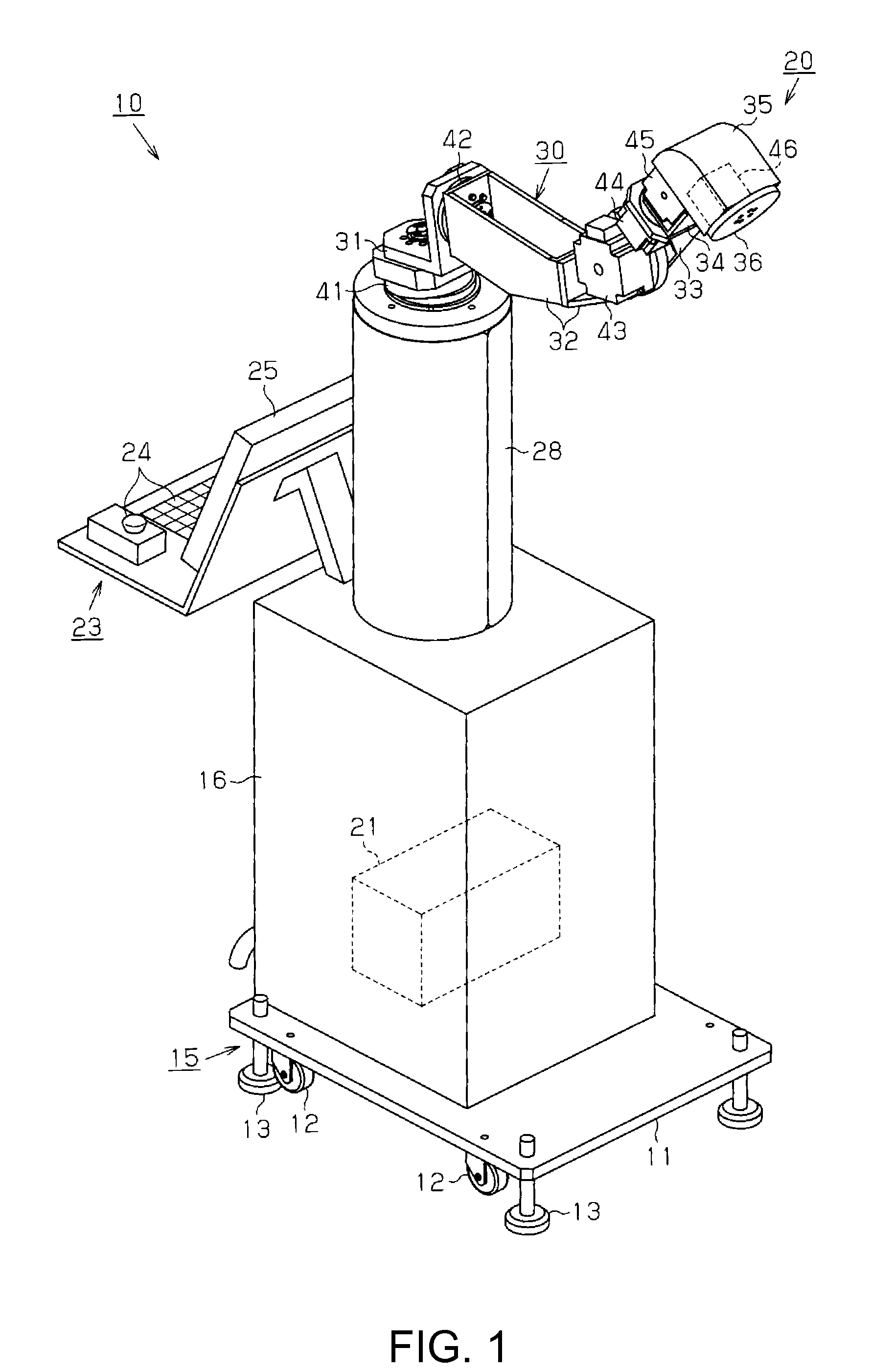
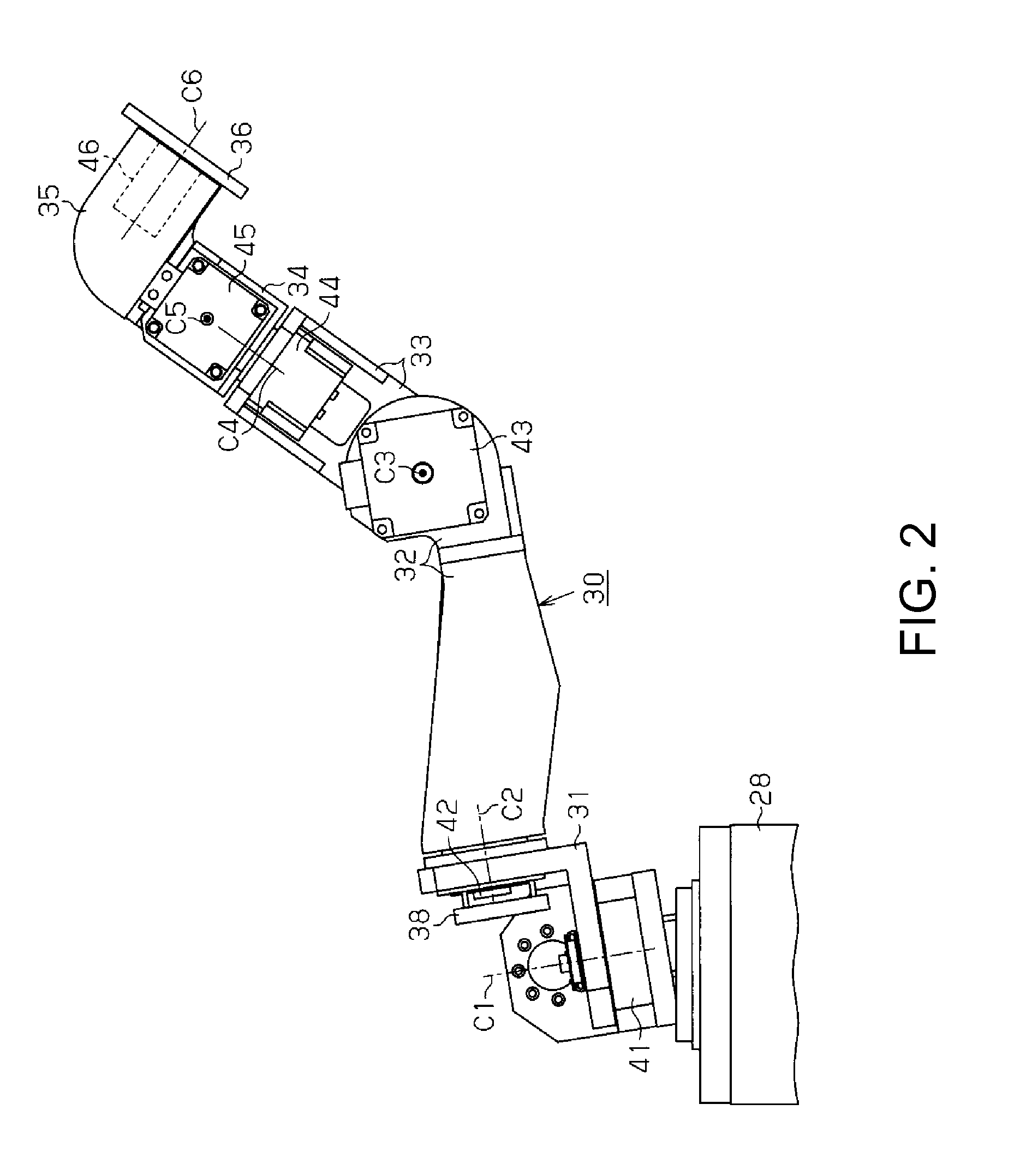
[0028]Hereinafter, a robot controller, an easy installation-type robot, and a method of controlling the simple installation-type robot according to embodiments of the invention will be described with reference to FIGS. 1 to 7.

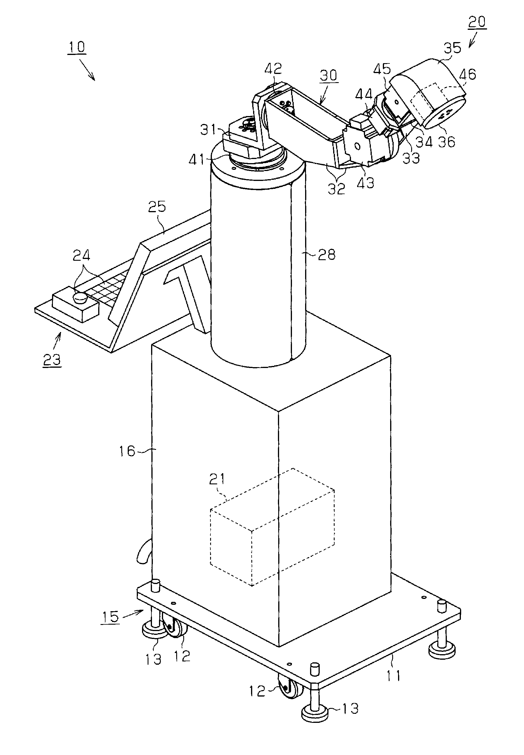
[0029]First, a schematic configuration of the simple installation-type robot will be described with reference to FIG. 1. As shown in FIG. 1, the simple installation-type robot 10 includes a carriage 15 as a moving device in which casters 12 and adjuster feet 13 are disposed at the corners of a support board 11 forming a rectangular shape. A stand 16, to which the robot 20 is fixed, is fixedly disposed on the support board 11 of the carriage 15, and a control device 21 configuring a robot controller that controls the operation of the robot 20 is disposed inside the stand 16. On the rear side of the stand 16, an input-output device 23 that is electrically connected to the control device 21 and configures the robot controller is disposed. The input-output device 2...


PUM


Abstract

A robot includes an angular velocity sensor that detects the vibration of a robot. A control device allows the robot to perform a trial operation and acquires the measurement result measured by the angular velocity sensor during the trial operation as vibration information and analyzes the acquired vibration information based on maker evaluating information that is stored in a database. In the maker evaluating information, vibration information and the operating speed appropriate to the installation situation of the robot at which the vibration information is measured are associated with each other. Then, the robot is operated at an operating speed selected based on the analysis result of the vibration information.

Description

BACKGROUND[0001]1. Technical Field[0002]The present invention relates to a robot controller that controls the operation of a robot mounted in a moving device, a simple installation-type robot in which the robot controller and a robot are mounted in a moving device, and a method of controlling the simple installation-type robot.[0003]2. Related Art[0004]Recently, in manufacturing industries, the movement toward automating the works performed by a worker for a work target by introducing a robot including a multi-joint arm to an assembly line has been brisk. In addition, high-mix low-volume production and shortening of the product cycle have progressed, and robots are frequently relocated according to corresponding recombination of production lines corresponding thereto.[0005]In JP-A-2010-64198, for easy implementation of the relocation of a robot, a simple installation-type robot is disclosed in which a robot and a controller of the robot are mounted on a carriage to which casters and...

Claims


Application Information

Patent Timeline
IPC IPC(8): B25J13/08B25J19/02
CPCB25J9/1653G05B2219/39182G05B2219/40294Y10S901/46B25J9/1694G05B15/02Y10S901/01G05B2219/40454
Inventor KIRIHARA, DAISUKE
Owner SEIKO EPSON CORP
Learn More