Storage apparatus and control method therefor
a storage apparatus and control method technology, applied in the field of storage apparatus and a control method of storage apparatus, can solve the problems of increasing the cost burden on the storage user, and achieve the effect of improving cost effectiveness and capacity efficiency
- Summary
- Abstract
- Description
- Claims
- Application Information
AI Technical Summary
Benefits of technology
Problems solved by technology
Method used
Image
Examples
first embodiment
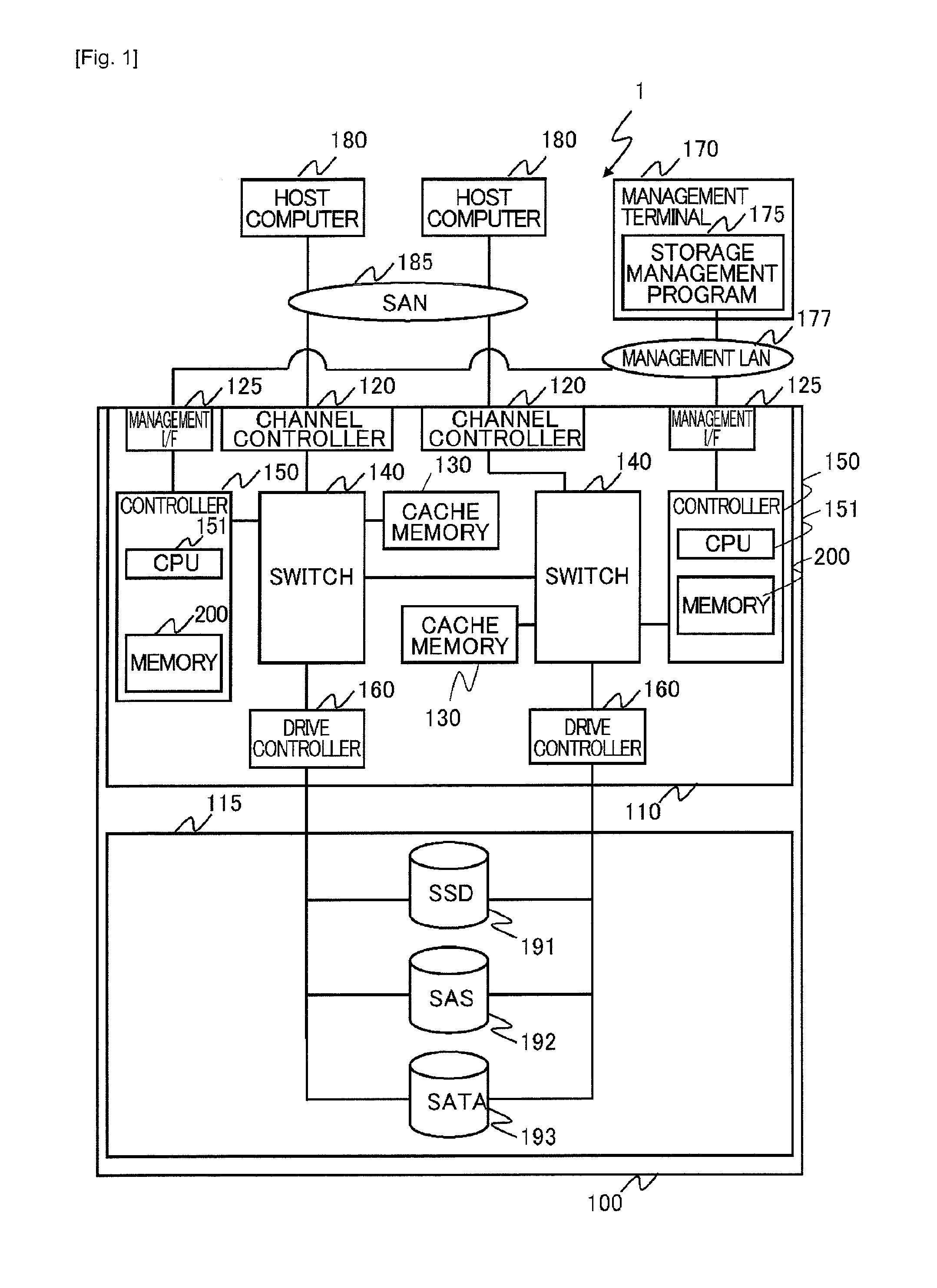
[0049]First of all, a first embodiment of the invention is described. FIG. 1 is a configuration diagram of a storage system according to an embodiment of the invention. In this embodiment, when a storage apparatus is operated under a tier control environment, a physical segment is allocated in a tier with a proper condition based on a change in an access frequency with respect to the physical segment after deduplication processing is performed.
[0050]As shown in FIG. 1, the storage system 1 includes a storage apparatus 100, host computers 180, and a management terminal 170. The host computer 180 is coupled to the storage apparatus 100 through a first communication network 185 so as to be capable of communication. The management terminal 170 is coupled to the storage apparatus 100 through a second communication network 177. In this embodiment, the first communication network 185 and the second communication network 177 are a SAN (Storage Area Network) and a LAN (Local Area Network) re...
second embodiment
[0220]Hereinafter, the description is given to another embodiment of the redundant segment tier control processing described in the first embodiment. FIG. 20 is a flowchart illustrating another example of the redundant segment tier control processing. This processing is performed in such a manner that the CPU 151 of the controller 150 executes the tier controller 201 and the redundant data management part 205 at the timing when the deduplication processing execution condition is fulfilled and the redundant data management such as snapshot processing is executed. Then, the inter-tier control based on the change in the access frequency to the physical segment 330 while in the redundant data management execution. In particular, the processing is characterized by the processing causing the physical segment 330 to remain also in the lower tier when the physical segment 330 is migrated to the upper tier after executing the deduplication processing.
[0221]Firstly, at S2001, the migration de...
third embodiment
[0233]In the first and second embodiments, the description is given to the control processing causing the storage apparatus 100 to be effectively operable by combining the inter-tier migration control and intra-tier copy control on the physical segment 330 if needed in the configuration in which multiple tiers whose storage devices have different types from each other are provided in the same storage apparatus 100.
[0234]In this embodiment, described is the deduplication control processing in the case where a virtual volume 300 being used by a host computer or the like is migrated between two different storage apparatuses 100.
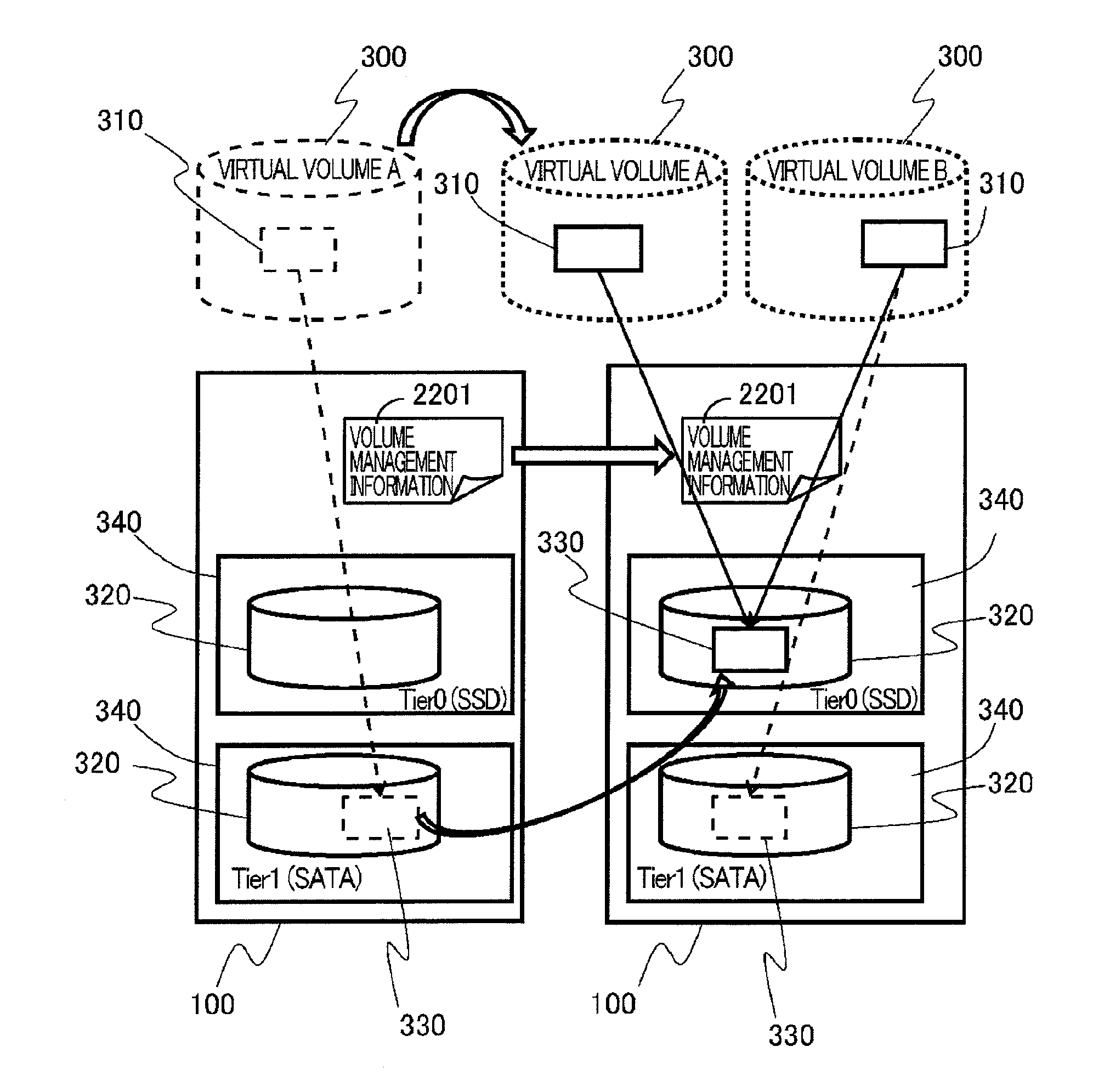
[0235]FIG. 22 is a schematic diagram showing the outline of the deduplication control processing when the volume is migrated between the storage apparatuses. The configuration of the storage apparatus 100 is basically similar to that of the storage apparatus 100 of the first embodiment exemplified in FIG. 1. The information needed for managing volumes such as a ...
PUM
 Abstract
Description
Claims
Application Information
 - R&D
- Intellectual Property
- Life Sciences
- Materials
- Tech Scout
- Unparalleled Data Quality
- Higher Quality Content
- 60% Fewer Hallucinations
Browse by: Latest US Patents, China's latest patents, Technical Efficacy Thesaurus, Application Domain, Technology Topic, Popular Technical Reports.
© 2025 PatSnap. All rights reserved.Legal|Privacy policy|Modern Slavery Act Transparency Statement|Sitemap|About US| Contact US: help@patsnap.com


