Meat cubing and skewering device

a skewer and meat technology, applied in the direction of meat cubing/cutting, meat shaping/cutting, manufacturing tools, etc., can solve the problems of not showing a means, affecting the ability of cutters, and creating significant friction, etc., to achieve wide range of cutting instrument spine thickness, low volume storage, and easy cleaning

Inactive Publication Date: 2012-11-08
MULCHI JR CHARLES LEE +1
View PDF13 Cites 15 Cited by
  • Summary
  • Abstract
  • Description
  • Claims
  • Application Information

AI Technical Summary

Benefits of technology

[0006]The present invention provides an efficient means of guiding the cutting of meat into cubes and then placing these cubes onto kebobs or skewers. Additionally, the design provides for easy cleaning and low volume storage of the device.
[0007]The device is composed of six sides which when fastened together form a generally cubical shape. The top side possesses apertures through which kebobs or skewers can be inserted. The four vertical sides are comprised of a series of mounted elongated rods or rollers that incorporate flexible bearing materials to allow for a wide range of cutting instrument spine thickness. The rods or rollers are spaced in such a way as to form an obvious pairing in which each roller is spaced very closely to one additional roller. This narrow spacing between any given pair of rollers serves as an auto-aligning cutting guide for a handheld knife. The larger gap between roller pairs allows the user to see what they are doing, view the movement and condition of the item they are cutting, and keep track of where they have already cut. The use of rollers also reduces cutting friction, minimizes the chance of damage to the roller surfaces caused by serrated cutting knives, and also prevents shedding of ...

Problems solved by technology

The prior art exhibits several limitations: (1) the guides permit for only one or two cutting axes provided the food item is not manually rearranged; (2) using simple slits within otherwise solid planes, particularly while cutting meat of uneven consistency, can create significant friction between the cutting kn...

Method used


Image

  • Meat cubing and skewering device
  • Meat cubing and skewering device
  • Meat cubing and skewering device

Examples


Embodiment Construction

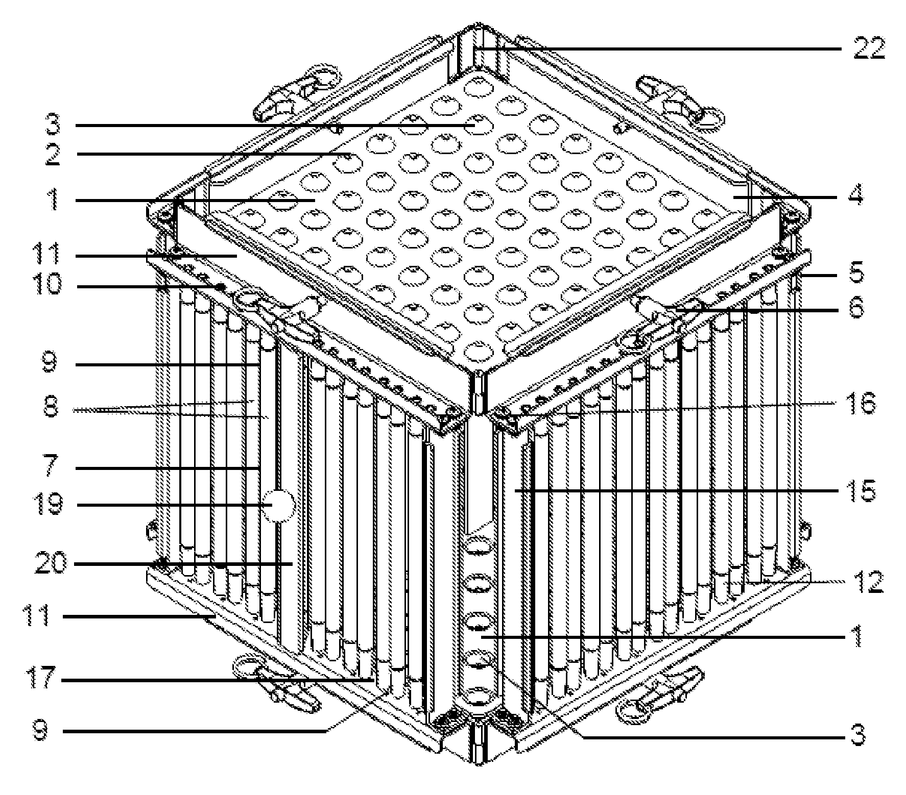
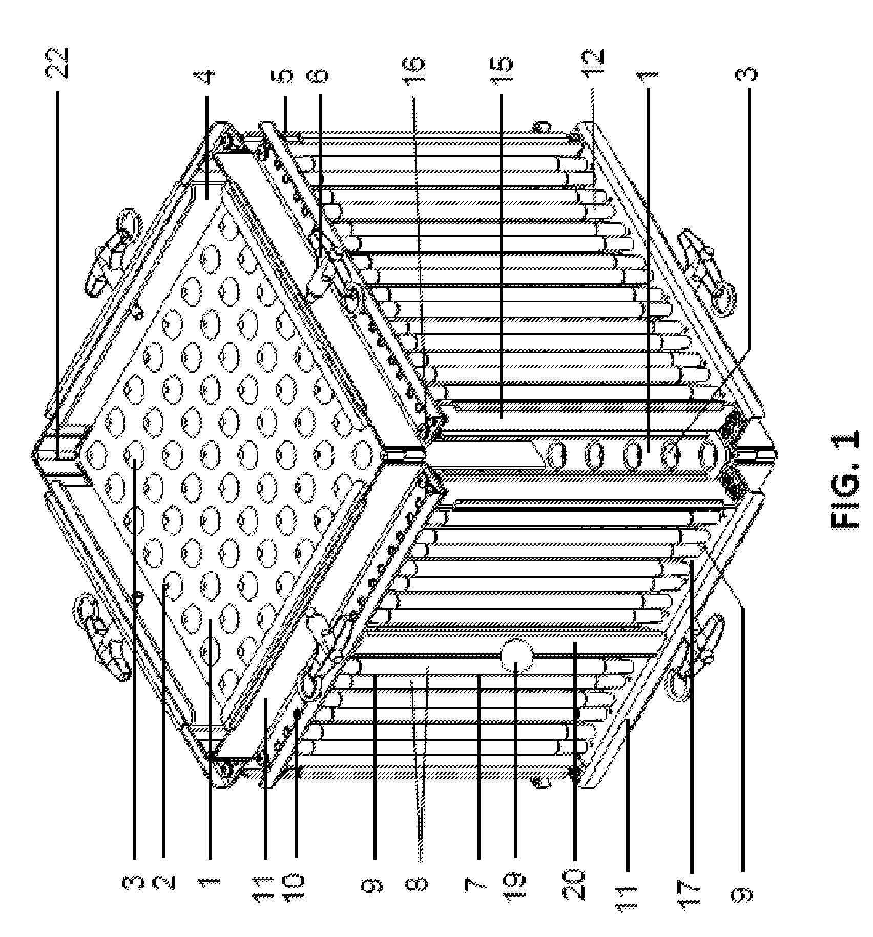
[0017]An elevated view of the meat cutting device, as shown in FIG. 1, illustrates all of its major parts. The identical top and bottom plates 1 are made up of an array of evenly spaced apertures 2 that are set off from the inter-aperture plane by a series of conically shaped dimples 3 that surround the apertures 2. The apertures 2 are set above the inter-aperture plane at the top and set below at the bottom. The purpose of the apertures 2 is to permit the insertion of skewers for the making of shish kebobs or Souvlaki. On the bottom plate, the conically shaped dimple 3 surrounding each aperture 2 assists in guiding a skewer head through the relatively narrow aperture. By better controlling the alignment of skewer heads along the bottom, there is less probability of skewer interference with one another and thus less probability of multiple-skewered or non-skewered meat cubes near the bottom of the device. The top and bottom plates 1 also have four vertical walls 4 on their sides. Th...


PUM

PropertyMeasurementUnit
Angleaaaaaaaaaa
Angleaaaaaaaaaa
Lengthaaaaaaaaaa

Abstract

This meat cubing and skewering device utilizes a low friction guide system along two axes to facilitate the cutting of meat slabs into cubes for the purpose of making shish kebobs or Souvlaki. The device also provides for a means of skewering the cubes using an array of dimpled apertures in equivalent top and bottom plates that minimizes the multiple skewer interference that can occur at the bottom of such devices. The four vertical sides are made up of a series of paired elongated rods or rollers that serve as cutting guides and these four vertical sides are hinged in such a way as to keep them all together and yet fold flat for easy storage and cleaning within a dishwasher.

Description

BACKGROUND OF THE INVENTION[0001]1. Field of the Invention[0002]The invention relates generally to the quick and efficient cutting of meat into cubes and the subsequent placement of these cubes onto kebobs and / or skewers.[0003]2. Description of the Prior Art[0004]There are a few meat cutting devices in the prior art, on a non-industrial scale, that facilitate the cubing of meat and subsequently placing the cubes onto kebobs. Most relevant to the present invention is the Panaritis patent from 1977, U.S. Pat. No. 4,056,026. It discloses a device which guides the cutting of meat with a handheld knife along two axes. Thus, if meat placed within the device is already cut into roughly equal slabs and these slabs are laid upon their side one on top of the other, the device can create meat cubes via two equal and vertical series of cuts at a 90° angle from each other. Furthermore, apertures placed at the top of the device can be utilized for the placement of kebobs that will skewer all the ...

Claims


Application Information

Patent Timeline
IPC IPC(8): A22C17/00B26D3/18
CPCA22C17/002B26B29/063A22C17/006Y10T83/8878
Inventor MULCHI, JR., CHARLES LEELEMBEROS, NICK PETE
Owner MULCHI JR CHARLES LEE
Why Eureka
Try Eureka