System and method for drying drill cuttings

a drilling cutting and cutting technology, applied in the direction of separation process, lighting and heating apparatus, borehole/well accessories, etc., can solve the problems of drilling fluid loss, significant cost to drill operators, and difficulty in removing drilling fluid and hydrocarbons, so as to improve the flow of drilling fluid through the shaker screen and the effect of separation of drilling fluid

Inactive Publication Date: 2012-11-08
FP MARANGONI INC
View PDF10 Cites 23 Cited by
  • Summary
  • Abstract
  • Description
  • Claims
  • Application Information

AI Technical Summary

Benefits of technology

[0021]a) applying an effective air vacuum pressure to a lower surface of a shaker screen supporting drilling fluid contaminated drill cuttings to enhance the flow of drilling fluid through the shaker screen and the separation of drilling fluid from drill cuttings;
[0024]In another embodiment, the method includes the step of applying an effective volume of air to the upper surface of the shaker screen to enhance the flow of drilling fluid through the shaker screen and the separation of drilling fluid from drill cuttings.

Problems solved by technology

The loss of drilling fluids presents several expensive challenges to the energy exploration industry as a result of the loss of drilling fluids to the formation and / or from the disposal of drilling detritus or cuttings that are contaminated with drilling fluid.
With some drilling fluids having values in excess of $1000 per cubic meter, the loss of such volumes of fluids represents a substantial cost to drill operators.
One particular problem is the removal of drilling fluid and any hydrocarbons from the formation that may be adhered to the drill cuttings (collectively “fluids”) at the surface.
However experience shows that the most aggressive and best recovery technologies like the VBC, and vacuum systems often produce a recovered fluid that must be processed by further equipment such as a scrolling centrifuge to remove very fine drilling detritus from the recovered fluid.
This adds additional cost for processing increases the complexity of fluid recovery.
Moreover, in excavation operations where less than about 3 cubic meters of losses are occurring on a daily basis, the current technologies generally price themselves outside of customer tolerances.
Unfortunately, these techniques have been unable to be cost effective for many drilling fluids as the use of diluting fluids often produces unacceptable increases in drilling fluid volume and / or changes in chemical consumption of the drilling fluid.

Method used


Image

  • System and method for drying drill cuttings
  • System and method for drying drill cuttings
  • System and method for drying drill cuttings

Examples


examples

[0048]A trial of the vacuum screen was made during a drilling operation at Nabors 49, a drilling rig in the Rocky Mountains of Canada. The trial was conducted while the rig was drilling and an oil-based Invert Emulsion drilling fluid was used. The drilling fluid properties from the well used during drilling are shown in Table 1 and are representative of a typical drilling fluid for a given viscosity.

TABLE 1Drilling Fluid PropertiesDepth4051 mT.V. Depth3762 mDensity1250 kg / m3Gradient12.3 kPa / mHydrostatic46132 kPaFunnel Viscosity45 s / lPlastic Viscosity10 Mpa · sYield Point2 PGel Strength1 / 1.5 Pa 10 s / 10 minOil / Water Ratio90:10HTHP16 mlCake1 mmChlorides375714 mg / lSand ConttraceSolids Cont12.88%High Density402 kg / m3 (9.46 wt %)Low Density89 kg / m3 (3.42%)Flowline42° C.Excess Lime22 kg / m3Water Activity0.47Electric Stability396 voltsOil Density820 kg / m3

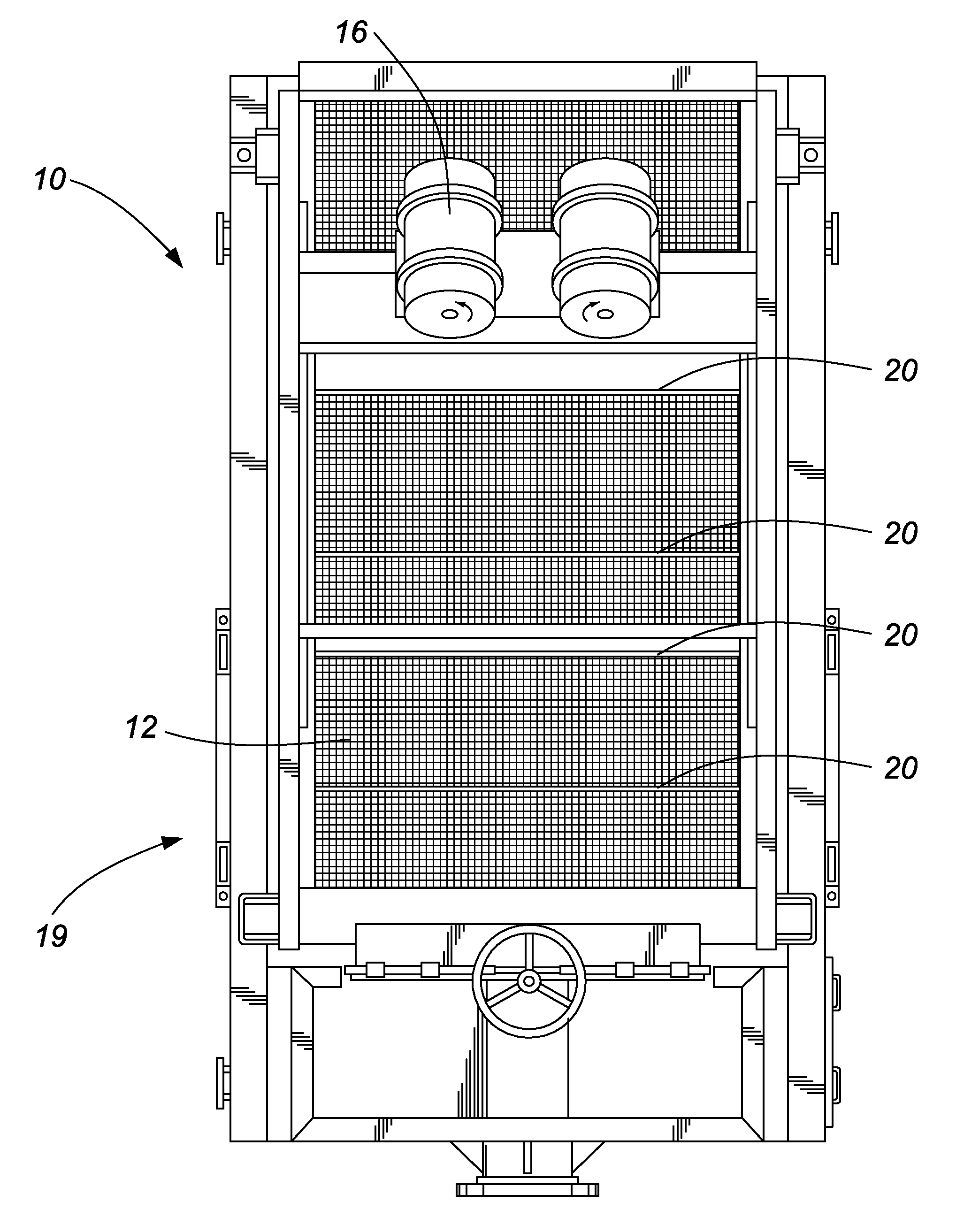
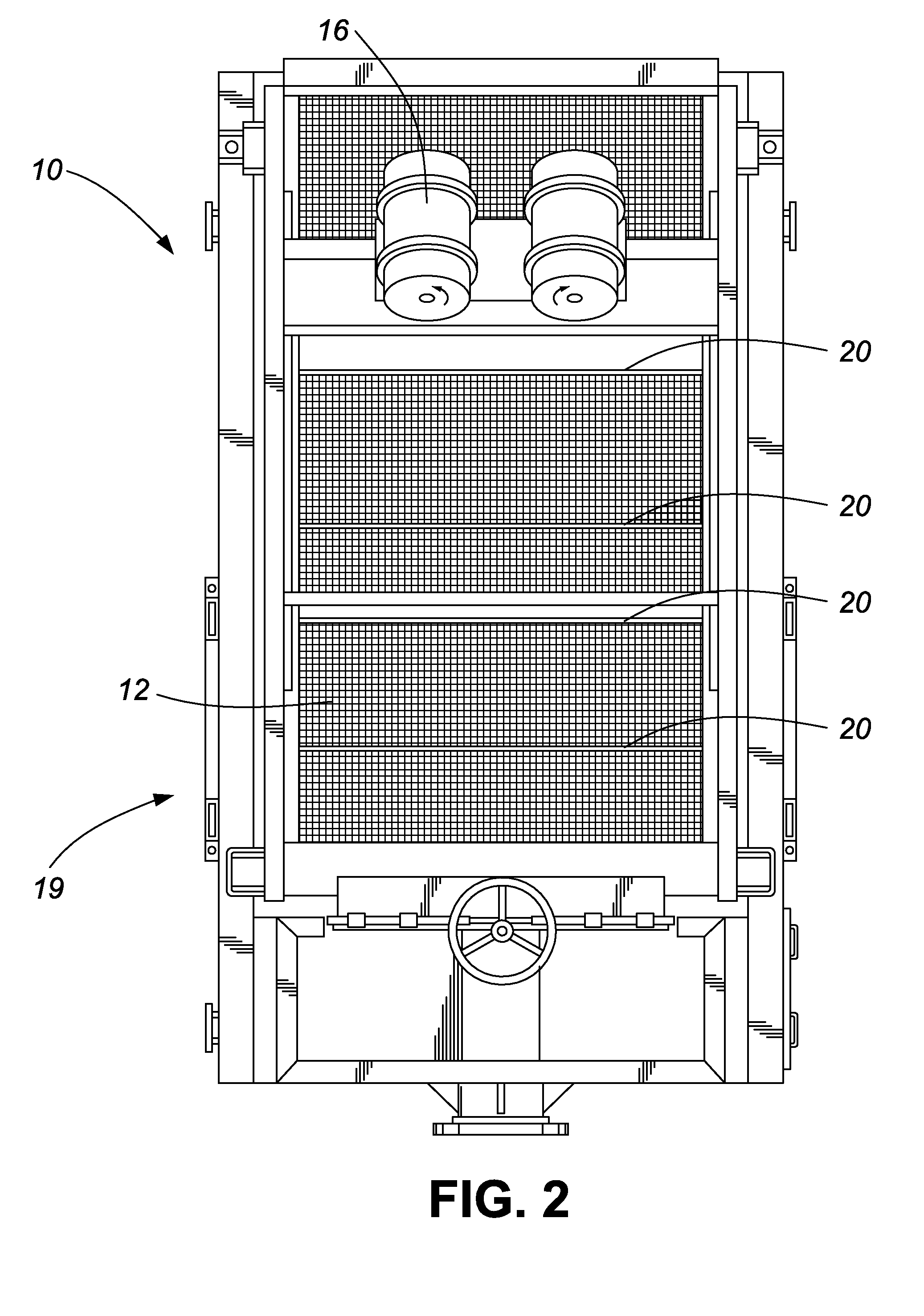
[0049]The test was conducted on a MI-Swaco Mongoose Shaker.

[0050]For the test, only one side of the vacuum system was connected so that rep...


PUM

PropertyMeasurementUnit
lengthaaaaaaaaaa
lengthaaaaaaaaaa
flow areaaaaaaaaaaa

Abstract

An apparatus and method for separating drilling fluid from drill cuttings using pressurized air and / or a vacuum. In a first embodiment, the apparatus provides for improved separation of drilling fluid from drill cuttings on a shaker, the shaker including a shaker screen, an air vacuum system and a drilling fluid collection system. In a second embodiment, the shaker includes a shaker screen and an air blowing system.

Description

CROSS-REFERENCE TO RELATED APPLICATIONS[0001]This application is a divisional of pending U.S. patent application Ser. No. 13 / 098,014 filed Apr. 29, 2011, which is a continuation of International patent application PCT / CA2009 / 001555 filed on Oct. 29, 2009 which designates the United States and claims the benefit under 35 U.S.C. §119 (e) of U.S. Provisional Patent Application Ser. No. 61 / 109,365, filed on Oct. 29, 2008. All prior applications are herein incorporated by reference in their entirety.FIELD OF THE INVENTION[0002]The invention describes systems and methods for separating drilling fluid from drill cuttings using pressurized air and / or a vacuum.[0003]The loss of drilling fluids presents several expensive challenges to the energy exploration industry as a result of the loss of drilling fluids to the formation and / or from the disposal of drilling detritus or cuttings that are contaminated with drilling fluid. In the context of this description, “drilling fluid” is both fluid pr...

Claims


Application Information

Patent Timeline
Patent Type & Authority Applications(United States)
IPC IPC(8): E21B21/06B01D33/03
CPCB07B1/28F26B17/26B01D29/117B07B13/16F26B5/12E21B21/065B01D35/02
Inventor POMERLEAU, DANIEL GUY
Owner FP MARANGONI INC
Why Eureka
Try Eureka