
Joint with heat-shielding element

a technology of heat shielding element and joint, which is applied in the direction of fluid pressure sealing joints, sleeve/socket joints, mechanical equipment, etc., can solve the problems of affecting the service life of the joint, so as to facilitate convective heat transfer, minimize the exposure of the flange, and facilitate the effect of convective heat transfer

Inactive Publication Date: 2012-11-08
BLUESCAPE CLEAN FUELS LLC
View PDF3 Cites 5 Cited by
  • Summary
  • Abstract
  • Description
  • Claims
  • Application Information

AI Technical Summary

Benefits of technology

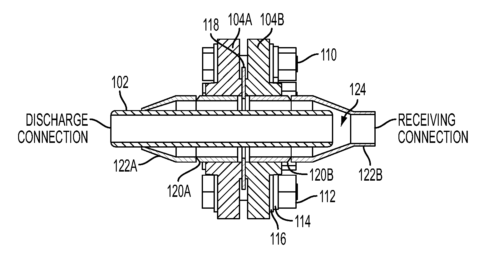
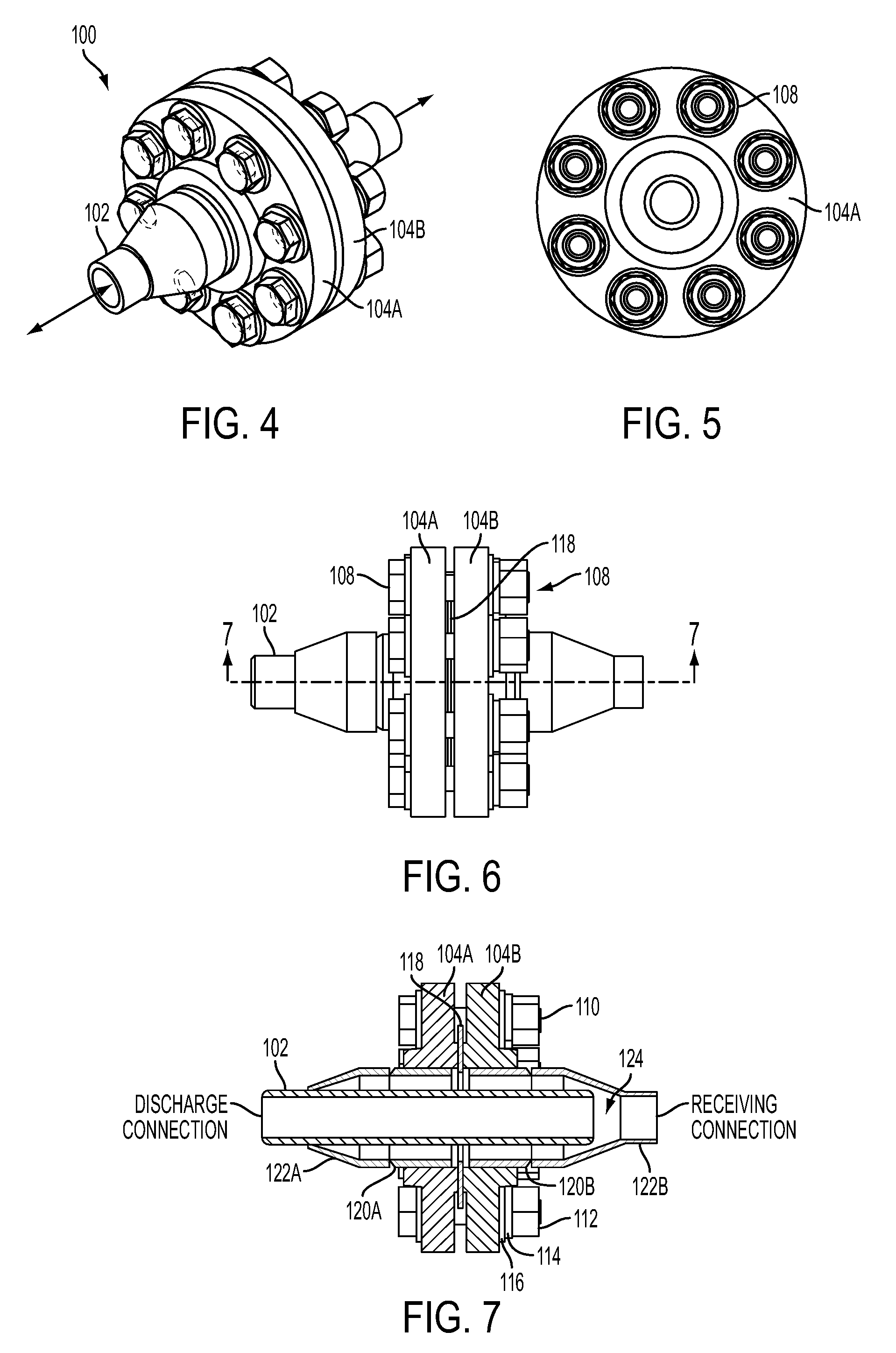
[0012]In operation, the flow of hot gases or fluids heats the walls of the fluid conduit by forced convection, but because of the gap between the fluid conduit and the flanges, it partially insulates the joint that is external to the conduit. Moreover, the added surface area of the flared connection and larger components provides greater surface exposure to surrounding outside air, which facilitates convective heat transfer to the bulk air near the flange.
[0013]This arrangement thus described protects the joint flange, gasket, and fasteners from the intense heat of the gases or fluids flowing through the pipes and fluid conduit. The flange and gasket temperatures are appreciably lower than the internal fluid conduit wall temperature under nominal operating conditions as a result of the use of the present invention.
[0014]In accordance with another embodiment of the present invention, a reducing passage / conduit is installed internally, separating a very hot steam flow from the flanged connection to minimize the exposure of the flange, gasket, and fasteners to the direct heat from the flowing gases and fluids in the conduit.
[0015]The invention not only solves many of the technological problems observed in connections as discussed above, but it is also economically cost-effective. For example, the direct capital cost of using a one standard size larger flange with sleeve and reducers is generally lower than using an incrementally higher-rated regular-size flange that is rated for the higher heat and pressure of the gases and fluids in the connected pipe sections. Generally, the marginal increase in capital cost for the larger / additional flanged components and / or reducers used according to the present invention is at least comparable to the cost required for high temperature-resistant fasteners and gaskets that would otherwise be required without the present invention. Further cost savings are observed by the elimination of additional maintenance required in continuous high-temperature operations, such as the required re-tensioning of fasteners (which may also simply be impossible or prohibitively difficult to do in certain applications).
[0016]Inherent in the design of the present invention, the fluid conduit protrudes into the receiving end of the flanged connection; thus it is possible to disassemble the connection by separating the components axially, using, for example, the proper pipe fittings up or downstream to allow for axial separation.
[0017]It is, therefore, a principle object of the present invention to provide a joint for connecting pipe sections in a manner that reduces the heat transfer from the gases or fluids flowing in the pipes to the flange components. That object, and other advantages of the present invention, are embodied, as fully described in more detail herein, by a first pipe section having an inside diameter; a first reducer fitting having first and second ends, the first end having an inside diameter substantially the same as the inside diameter of the first pipe section and the second end having an inside diameter smaller than the diameter of the first end, and wherein the first end is connected to an end of the first pipe section; a first flange attached to the first pipe section and having means for connecting the first flange to a second flange; and a fluid conduit positioned inside at least a portion of the first pipe section and the first reducer fitting, wherein the fluid conduit forms an annular space defined by the outside surface of the fluid conduit wall and the inner walls of the first pipe section and the first reducer fitting.

Problems solved by technology

Joining pipe sections or reactor inlets and outlets under those conditions is usually accomplished with flanges and gaskets, but since portions of those joints and gaskets are exposed to the high-temperature, high-pressure gases and fluids flowing past them, they are susceptible to problems, many of which are caused directly or indirectly by forced convective heat transfer from the fluid to the flanges, gaskets, and fasteners.
Moreover, fasteners can become loose due to the elongation of the fastener material when exposed to sustained high temperatures.
Those conditions can cause the connection at the joint to fail.
And, because it can be prohibitively expensive and time consuming to maintain such devices operating under those conditions, it is desirable to eliminate or minimize those heat-related problems.
Additionally, high temperature environments increase the rating requirement for flanges, which increases the capital cost for the entire joint.
But even using the highest rated devices for a particular application, the problem of sealing the devices remains problematic.
A typical solution to the above-problems, when encountered, is to fabricate a specialty fastener or gasket, but such custom devices often just address problems that are identified.
One-off or custom solutions are expensive and may not satisfy all of the unique requirements for the operation if the user fails to identify all of the causes of the problems.

Method used


Image

  • Joint with heat-shielding element
  • Joint with heat-shielding element
  • Joint with heat-shielding element

Examples


Embodiment Construction

[0028]Several preferred embodiments of the present invention are described for illustrative purposes, it being understood that the invention may be embodied in other forms not specifically shown in the drawings. The figures will be described with respect to the structure and functions that achieve one or more of the objects of the invention and / or receive the benefits derived from the advantages of the invention as understood by persons skilled in the art or explicitly set forth herein.

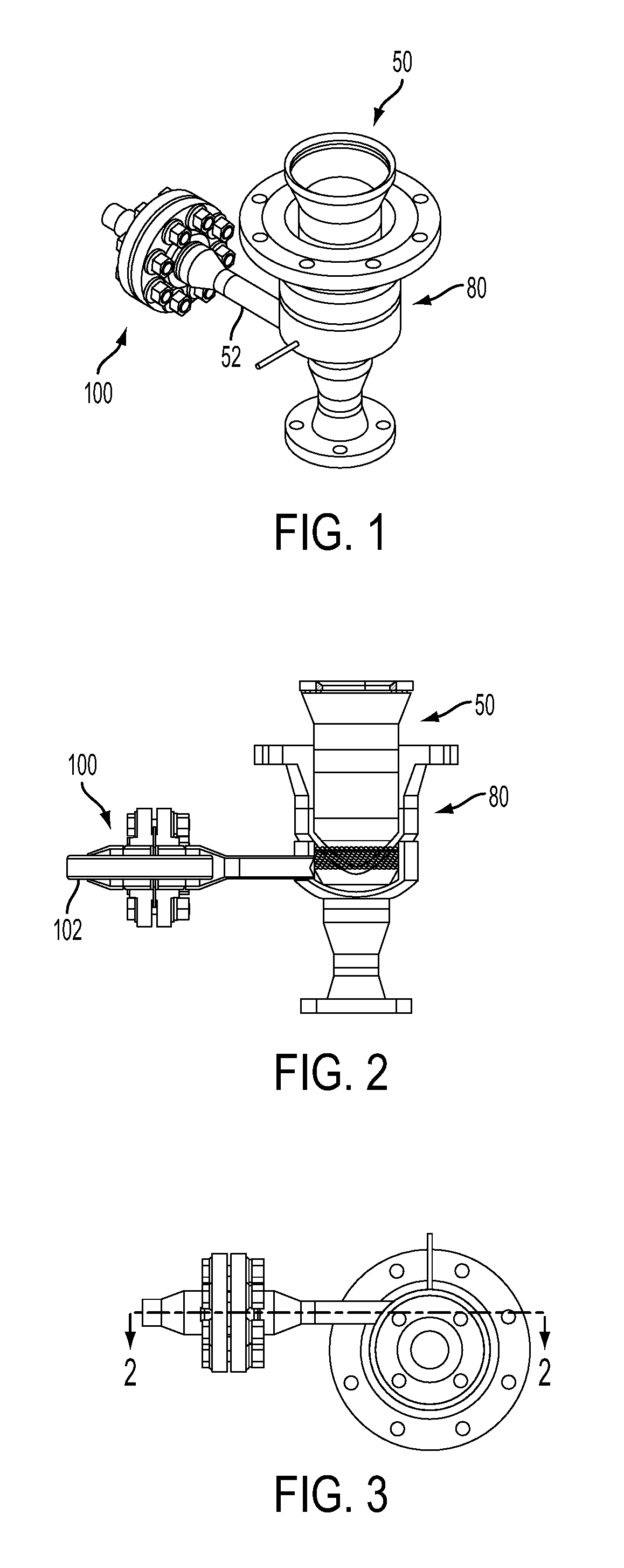
[0029]Turning first to FIG. 1, shown therein is perspective view diagram of a heat-shielded pipe joint 100 according to the present invention, for connecting pipe sections, and is shown attached to a discharge assembly 50. For purposes of this description, the discharge assembly 50 essentially describes an apparatus inside a flange section 80. Also for purpose of this description, the pipe joint 100 (hereinafter “joint”) essentially describes an apparatus that includes a butt joint between the ends of...


PUM


Abstract

A joint for connecting pipe sections is provided in which a portion of the joint includes a first pipe section, a first reducer fitting section, a first flange attached to the first pipe section and having holes for receiving fasteners, and a fluid conduit (such as a pipe sleeve) positioned inside at least a portion of the first pipe section and the first reducer fitting, wherein the fluid conduit forms an annular space defined by the outside surface of the fluid conduit wall and the inner walls of the first pipe section and the first reducer fitting. The annular space separates the heat-sensitive flange, a flange gasket, and the flange fasteners from high-temperature fluids flowing in the fluid conduit, thereby allowing for the use of lower rated and less expensive components than would otherwise be required in a direct heat contacting arrangement.

Description

BACKGROUND OF THE INVENTION[0001]1. Field of the Invention[0002]The present invention relates to welded flange-type connectors used to join pipe sections, and to heat-dissipating or heat-shielding devices for reducing heat-related problems at such joints.[0003]2. Description of the Related Art[0004]Butt welded, bolted, flange-type connectors have traditionally been used to join pipe sections. U.S. Pat. No. 5,163,715, for example, discloses a traditional face flange at a connecting end of a pipe section for joining with another flange at the end of a joining pipe section in an abutting manner. A face gasket is positioned between the flange faces prior to fastening the flanges to each other using bolts to form a seal between the interior surfaces of the flanges. The patent also discloses a polymer concrete liner interior of the pipe sections suitable for withstanding the effects of a geothermal fluid passing through the joint.[0005]U.S. Pat. No. 3,002,871 discloses a butt joint for jo...

Claims


Application Information

Patent Timeline
IPC IPC(8): F16L23/00
CPCF16L23/00F16L59/184F16L23/02
Inventor BEN-REUVEN, MOSHEARAUJO, BRUNO E.
Owner BLUESCAPE CLEAN FUELS LLC
Learn More