Image processing device, image processing method, and program

a technology of image processing and image conversion elements, applied in the field of image processing devices, image processing methods, and programs, can solve the problems of image quality deterioration, signal-to-noise ratio worsening, and the upper limit of the amount of electrical charge accumulated in the photoelectric conversion element, so as to reduce blurring, reduce signal noise, and reduce the effect of blurring

Inactive Publication Date: 2012-11-08
SONY SEMICON SOLUTIONS CORP
View PDF8 Cites 99 Cited by
  • Summary
  • Abstract
  • Description
  • Claims
  • Application Information

AI Technical Summary

Benefits of technology

[0046]According to the example of the present disclosure, a device and a method are achieved that generate an image with reduced blurring and a wide dynamic range based on a single captured image. Specifically, the device includes an image capture element that outputs long exposure time pixel information and short exposure time pixel information based on image capture processing under a control that provides different exposure times for individual pixels, and also includes an image correction portion that inputs the pixel information that the image capture element has output and generates a corrected image by performing image stabilization and dynamic range expansion processing.
[0047]The image correction portion generates a long exposure time image in which the pixel values have been set on the assumption that all of the pixels have been exposed for a long time and a short exposure time image in which the pixel values have been set on the assumption that all of the pixels have been exposed for a short time, computes a point spread function (a PSF) that corresponds to the long exposure time image as a long exposure time image PSF, and generates the corrected image by using the short exposure time image, the long exposure time image, and the long exposure time image PSF. The corrected image is generated as a wide dynamic range image that utilizes the pixel information for the long exposure time image and the pixel information for the short exposure time image. Utilizing the pixel information for the short exposure time image, in which there is little blurring, also makes the corrected image a high quality corrected image in which the blurring is suppressed.

Problems solved by technology

However, there is an upper limit to the amount of the electrical charge that is accumulated in the photoelectric conversion element, and when more than a fixed amount of light is received, the amount of the accumulated electrical charge reaches a saturation level, such that what are called blown out highlights, which are set at a saturated brightness level, occur in regions of the photographic subject where the brightness is greater than a fixed value.
However, in capturing an image of a subject that has a mixture of bright regions and dark regions, using a fast shutter speed means that the exposure time will not be sufficient for the dark portions, so the signal-to-noise ratio worsens, and the image quality deteriorates.
In this manner, using a plurality of images for which the exposure times have been changed makes it possible to produce the wide dynamic range image (the high dynamic range (HDR) image), but the problems that are described below, for example, occur in the processing that is based on the plurality of the images.
First problem: The image capture must be performed a plurality of times.
Second problem: A plurality of images that have been captured at different times are combined, and captured image data with long exposure times are used, so the process is vulnerable to the effects of camera instability.
However, with these configurations, there is a problem in that the exposure times vary from one pixel to the next, so the long exposure time pixels are more susceptible to blurring than the short exposure time pixels, and it is difficult to completely eliminate the effects of camera instability.
However, even with the disclosed technique, it is necessary to perform image capture twice, once with a short exposure time and once with a long exposure time.
However, in order for the amount of blurring to be estimated when the exposure times are varied one line at a time, the image must be captured by combining pixels with at least three different exposure times, giving rise to a problem of blurring in the vertical direction.
However, there is a problem in that the short exposure time image capture must be performed a plurality of times, which makes the control more complicated.

Method used


Image

  • Image processing device, image processing method, and program
  • Image processing device, image processing method, and program
  • Image processing device, image processing method, and program

Examples


Embodiment Construction

[0062]Hereinafter, preferred embodiments of the present disclosure will be described in detail with reference to the appended drawings. Note that, in this specification and the appended drawings, structural elements that have substantially the same function and structure are denoted with the same reference numerals, and repeated explanation of these structural elements is omitted.

[0063]Hereinafter, an image processing device, an image processing method, and a program according to the present disclosure will be explained with reference to the drawings. The explanation will cover the items below in order.

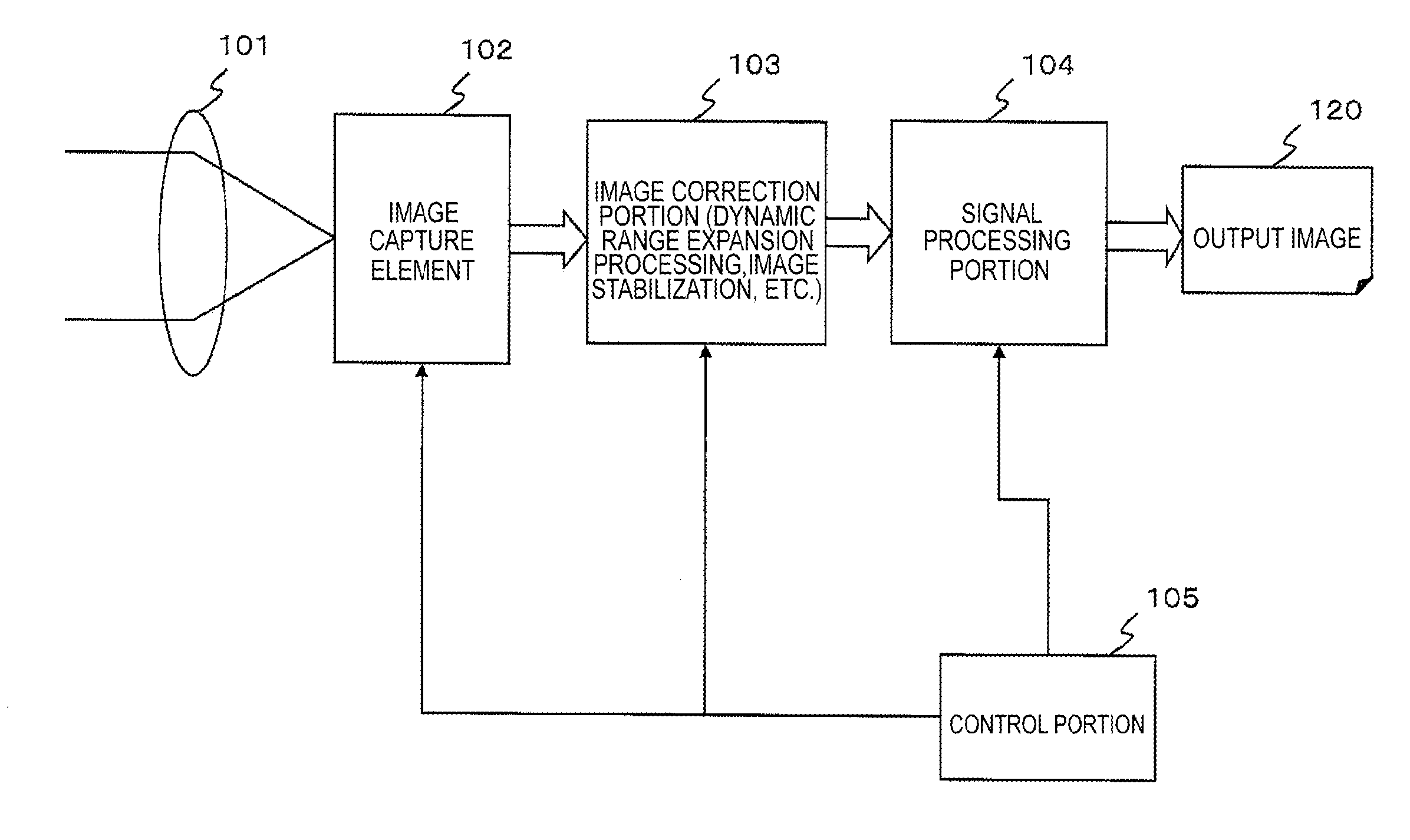
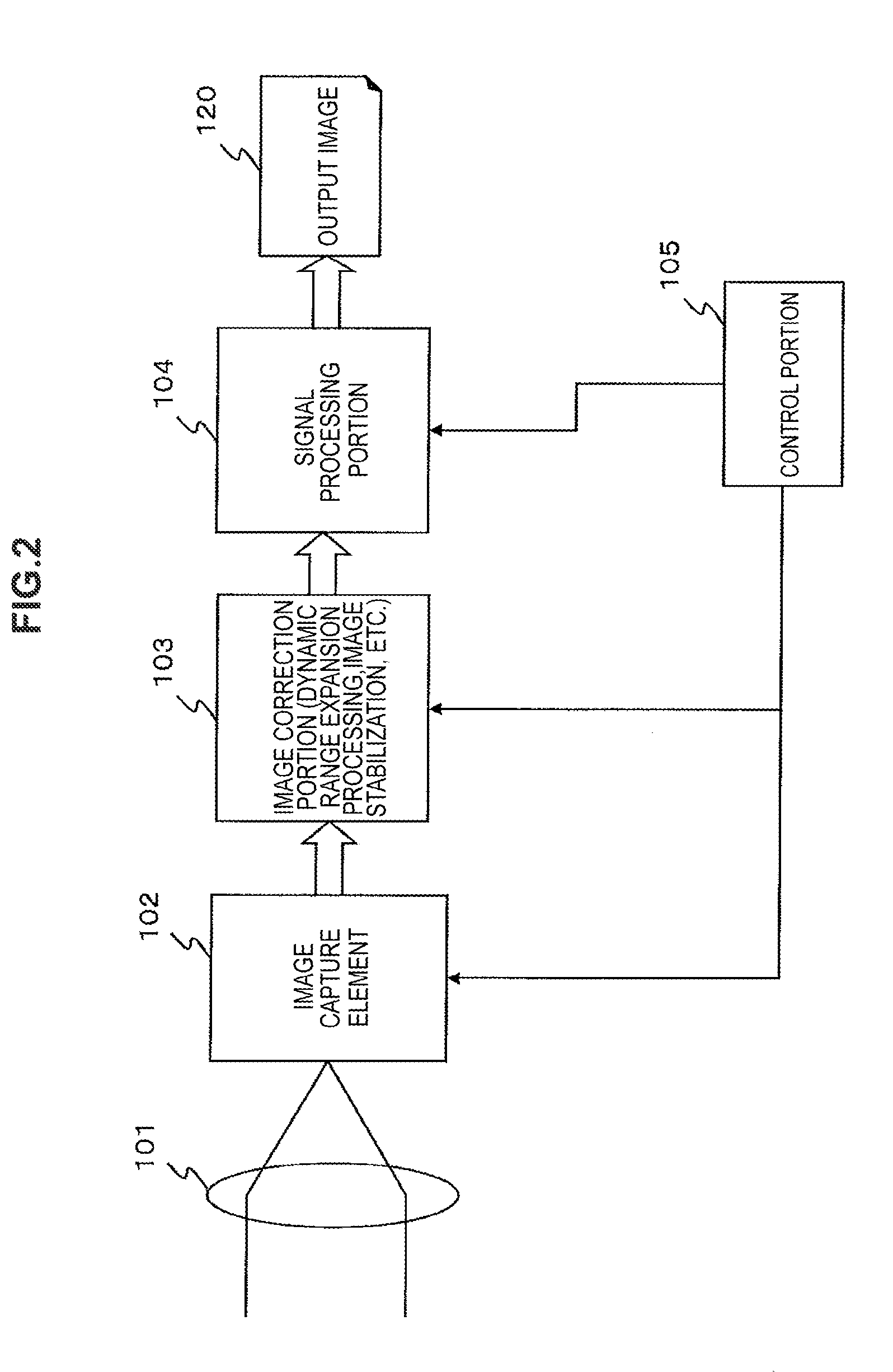
[0064]1. Example of an overall configuration of the image processing device

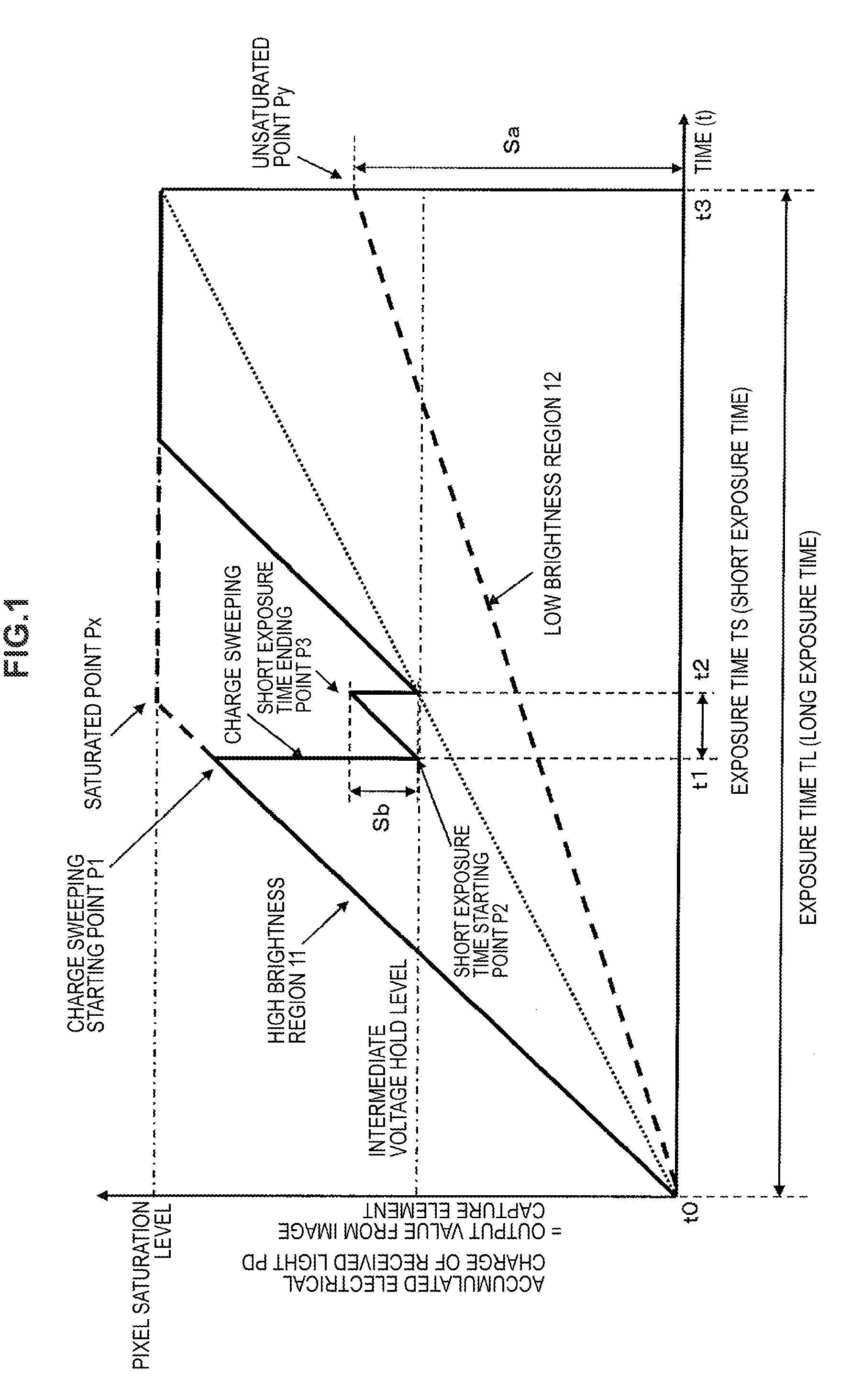
[0065]2. Example of a configuration of an image capture element

[0066]3. Details of a configuration of and processing by an image correction portion

[0067](3-1) Details of a configuration of and processing that is performed by an interpolation processing portion

[0068](3-2) Details of a configuration of and proces...


PUM


Abstract

Long and short exposure time pixel information are input to pixel information. A long exposure time image set with the pixel values assuming all of the pixels have been exposed for a long time and a short exposure time image set with the pixel values assuming all of the pixels have been exposed for a short time are generated. A point spread function corresponding to the long exposure time image is computed as a long exposure time image PSF. A corrected image is generated using the short exposure time image, the long exposure time image, and the long exposure time image PSF. The corrected image is generated as a wide dynamic range image utilizing the pixel information for the long and short exposure time image. Utilizing the pixel information for the short exposure time image with little blurring, makes the corrected image a high quality corrected image with little blurring.

Description

BACKGROUND OF THE INVENTION[0001]The present disclosure relates to an image processing device, an image processing method, and a program. In particular, the present disclosure relates to an image processing device, an image processing method, and a program that generate an image with a dynamic range that is wide.[0002]A solid image capture element that is used in a video camera or a digital still camera, such as a CCD image sensor or a complementary metal oxide semiconductor (CMOS) image sensor, accumulates an electrical charge that corresponds to the amount of incident light and performs a photoelectric conversion that outputs an electrical signal that corresponds to the accumulated electrical charge. However, there is an upper limit to the amount of the electrical charge that is accumulated in the photoelectric conversion element, and when more than a fixed amount of light is received, the amount of the accumulated electrical charge reaches a saturation level, such that what are c...

Claims


Application Information

Patent Timeline
Patent Type & Authority Applications(United States)
IPC IPC(8): H04N5/235
CPCH04N5/217H04N5/2355H04N9/045H04N5/265G06T5/50G06T2207/20224H04N5/2621G06T5/003H04N23/81H04N23/741H04N23/843H04N25/134
Inventor JO, KENSEIKAIZU, SHUNMITSUNAGA, TOMOO
Owner SONY SEMICON SOLUTIONS CORP
Why Eureka
Try Eureka