Gas Insulated Bus and Particle Removal Method for Gas Insulated Bus

a gas insulated bus and particle removal technology, which is applied in the direction of insulated conductors, rigid-tube cables, cables, etc., can solve the problems of increasing the temperature of the conduction, the reduction of the size of the gas insulated bus according to the reference 1, and the inability to take into account the suppression of an increase in the temperature of the insulating spacer part, so as to reduce the operation time of conditioned particles and increase the traveling speed of particles , the effect of reducing

Active Publication Date: 2012-11-08
HITACHI LTD
View PDF2 Cites 5 Cited by
  • Summary
  • Abstract
  • Description
  • Claims
  • Application Information

AI Technical Summary

Benefits of technology

[0022]According to the particle removal method according to the present invention, the metal container is installed at least in an inclined manner for conditioning for a particle. Thus, when a particle floated by an electric field falls down onto the inner surface of the metal container, gravity causes the particle to fall down onto the inner surface of a lower part of the metal container. That is, the position of the particle that repeatedly floats and falls moves to the lower expanded diameter part of the metal container. This enables an increase in the traveling speed of the particle. As a result, the operation time for conditioning

Problems solved by technology

However, a method for reducing the size of a gas insulated bus according to the Reference 1 fails to take into account a reduction in the size of the gas insulated bus with satisfying the insulation and conductivity performance requirements.
That is, the method fails to take into account suppression of an increase in the temperature of the insulating spacer part which is to be carried out to satisfy the conductivity performance requirement when the diameter of the metal container of the gas insulated bus is reduced.
For example, in connection with an increase in temperature during conduction, the JEC standard and the like specify that the temperature of the insulating spacer part is at most 105° C. Thus, an excessive reduction in the diameter of the metal con

Method used


Image

  • Gas Insulated Bus and Particle Removal Method for Gas Insulated Bus
  • Gas Insulated Bus and Particle Removal Method for Gas Insulated Bus
  • Gas Insulated Bus and Particle Removal Method for Gas Insulated Bus

Examples


embodiment 1

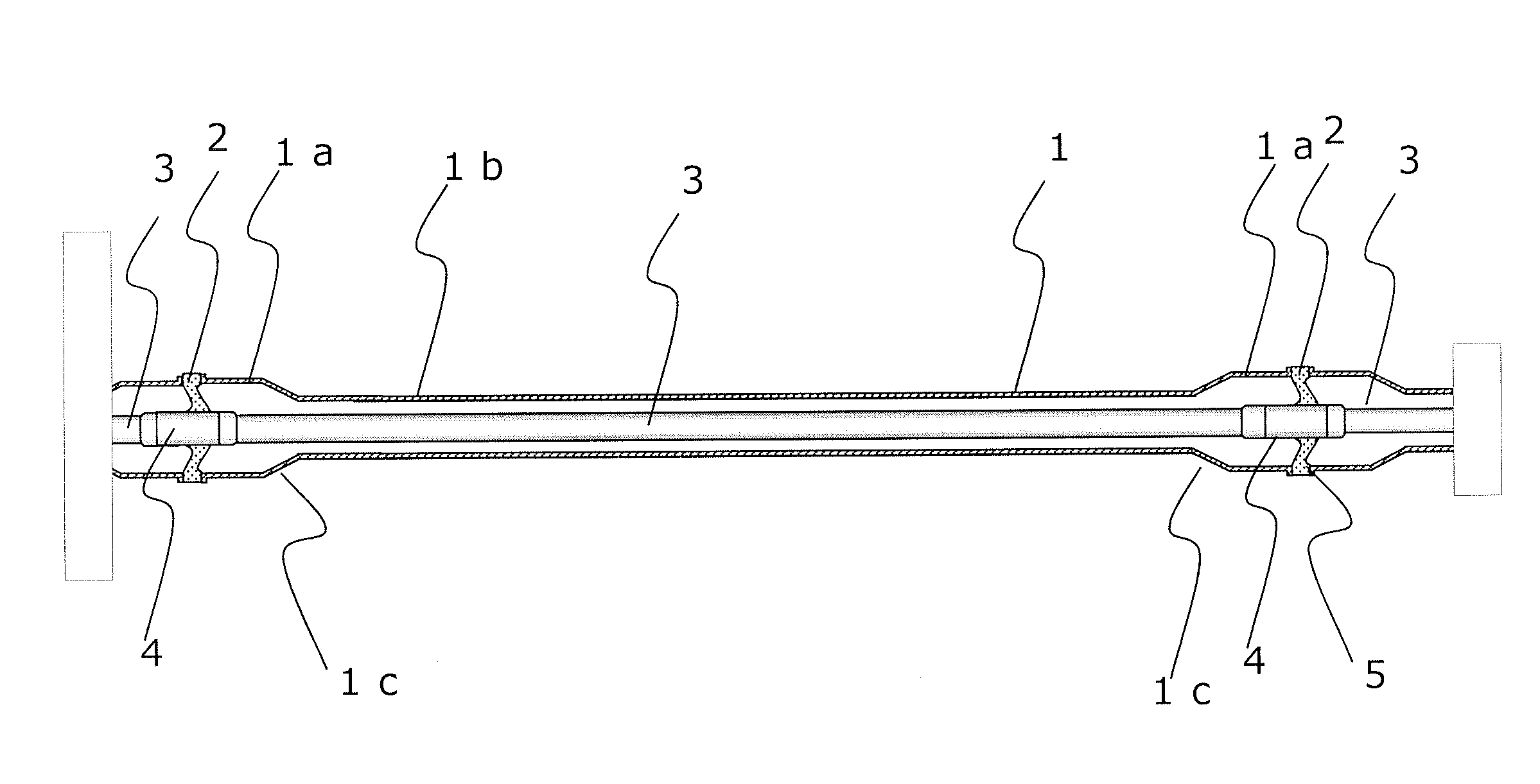
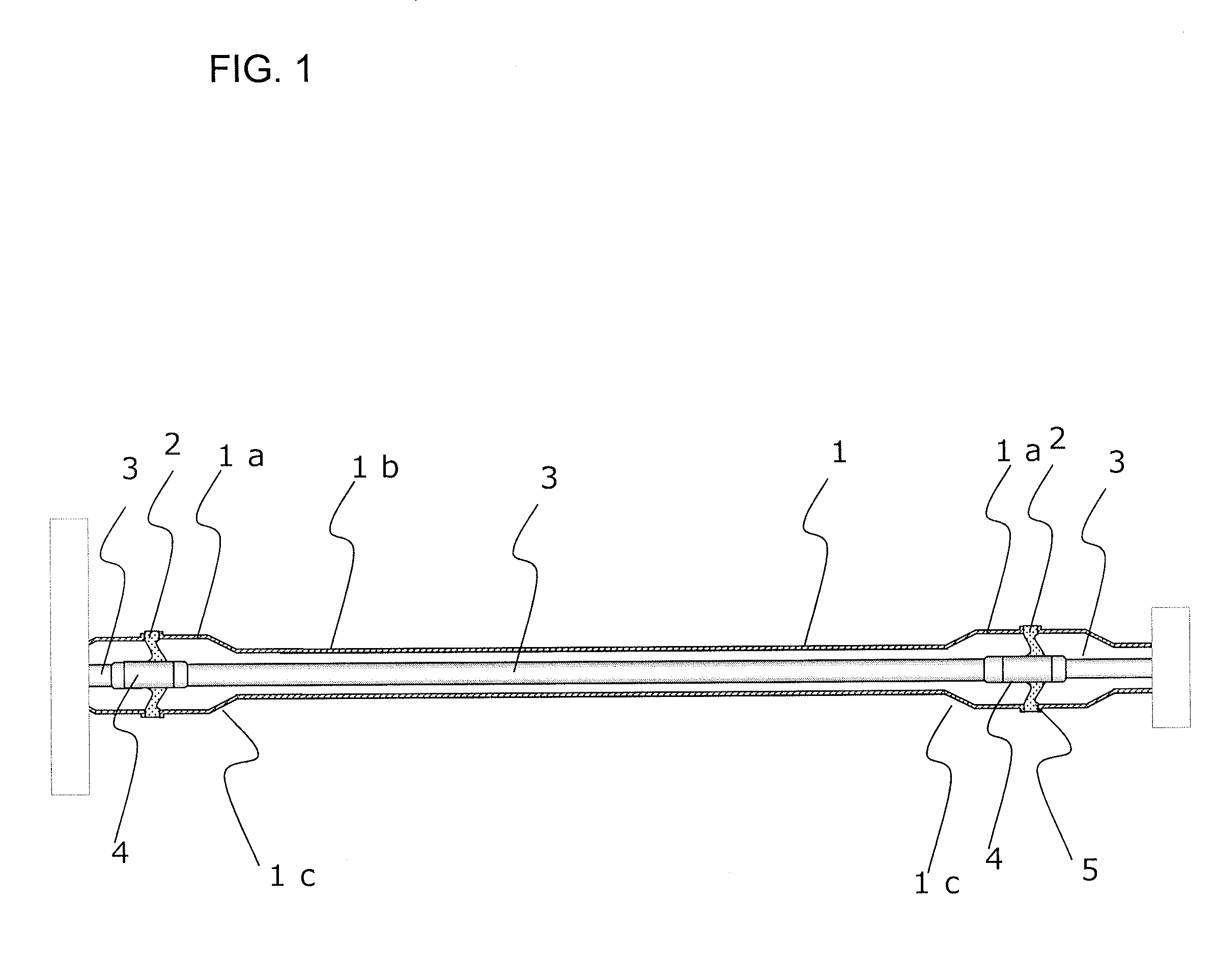
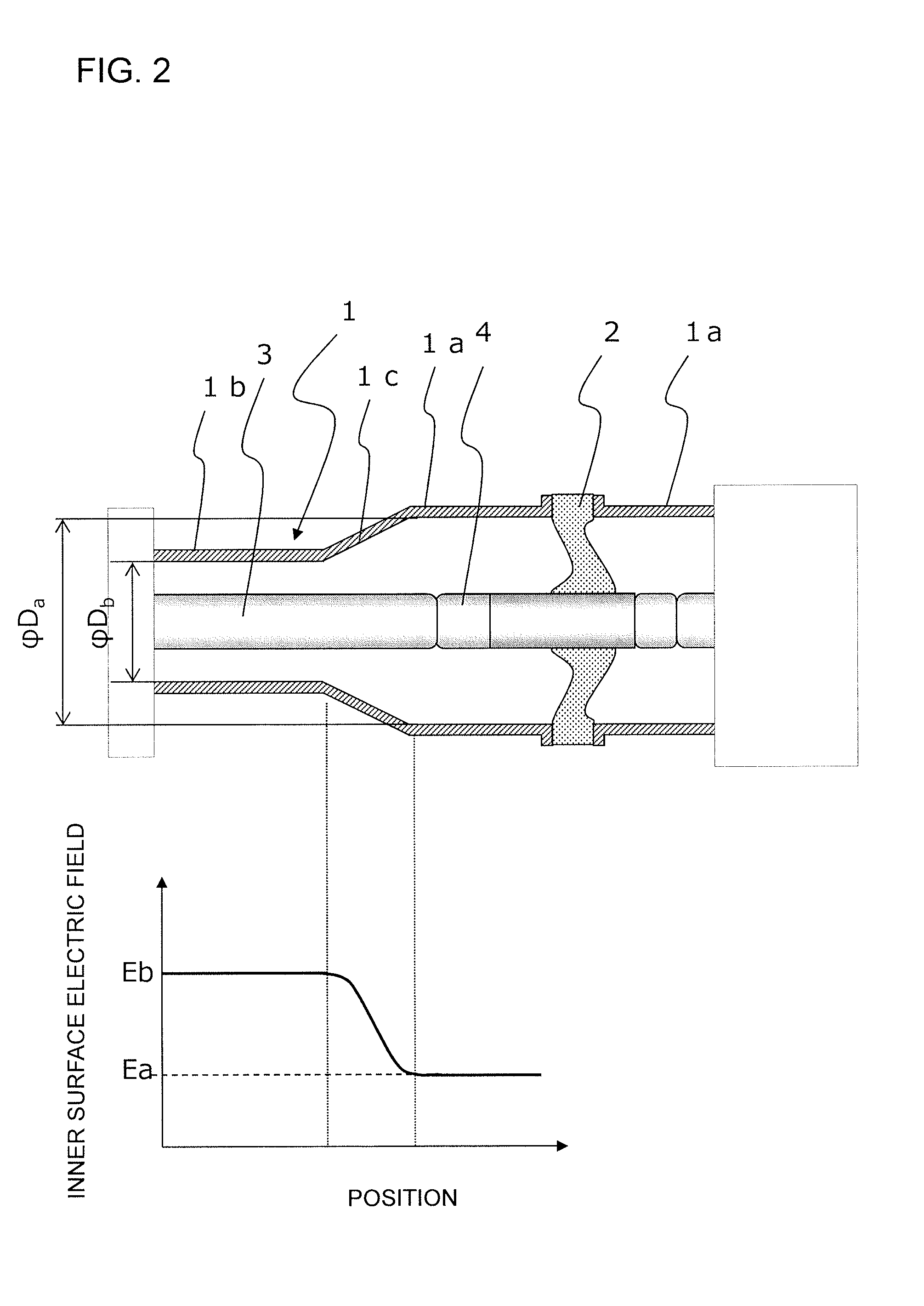
[0034]The present invention is applicable to gas insulated lines without any change. However, the present invention will be described based on a cross-sectional view of an embodiment of a gas insulated bus shown in FIG. 1. As shown in FIG. 1, the gas insulated bus is compactly configured to have a high-voltage conductor 3 supported, via insulating spacers 2 serving as an insulator, in a cylindrical metal container 1 in which a high-pressure SF6 gas is contained. Each of the insulating spacers 2 is formed of an epoxy resin, which has a high dielectric strength, and is shaped like a cone. A connection conductor 4 to which the high-voltage conductor 3 is connected is provided so as to penetrate a center of the insulating spacer 2. Furthermore, in use, the metal container 1 is grounded, though this is not shown in the drawings.

[0035]In the illustrated example, flanges 5 are provided at the respective opposite ends of the cylindrical metal container 1. The flanges 5 provided at the ends ...

embodiment 2

[0046]FIG. 4 shows a configuration of a device for conditioning for a particle according to an embodiment which is preferable for removing a particle by carrying out conditioning for a particle on the gas insulated bus shown in the embodiment in FIG. 1. FIG. 4(a) is a plan view of the device, and FIG. 4(b) is a cross-sectional view of the device as seen from a side of the device. FIG. 4 shows the device that simultaneously carries out conditioning for a particle on a plurality of (in the illustrated example, four) gas insulated buses 10. The present embodiment differs from the conditioning for a particle described with reference to FIGS. 1 to 3 in that as shown in FIG. 4(b), the opposite ends of the gas insulated bus 10 are installed on cradles 11a and 11b, which are different in height so as to incline the entire gas insulated bus for the conditioning for a particle.

[0047]That is, the conditioning for a particle described with reference to FIGS. 1 to 3 assumes that the gas insulate...

embodiment 3

[0050]In the embodiment in FIG. 1, the example is shown in which the cone-shaped insulating spacer is used at each of the opposite ends of the gas insulated bus. However, the present invention is not limited to this. The gas insulated bus may be configured using insulating spacers 15 one or both of which are shaped like a post. FIGS. 5(a) to 5(c) show gas insulated buses configured using such insulating spacers in various forms. The conical insulating spacer 2 has not only a function to support the high-voltage conductor 3 but also a function to keep the inside of the adjacent metal container 1 gas tight. In contrast, the post-shaped insulating spacer 15 has the function to support the high-voltage conductor 3 but not the function to keep the inside of the adjacent metal container 1 gas tight. Gas insulated buses are often coupled together for power transmission over a very long distance, and thus various shapes and arrangements of insulating spacers are used. If the gas insulated b...


PUM


Abstract

The present invention is provided to satisfy insulation and conductivity performance requirements, to reduce the size of a gas insulated bus, and also to make conditioning for a particle more reliable. In a gas insulated bus having a conductor supported in a cylindrical metal container via an insulator, insulating gas being contained in the metal container, the metal container has an expanded diameter part formed over a given range in an area of the metal container in which the insulator is positioned and a reduced diameter part formed over the entire area of the metal container except for the expanded diameter part. Thus, when the temperature of the insulator increases during conduction, heat from the insulator is transferred to the metal container via a large space in the expanded diameter part and released to the air through a large outer surface of the expanded diameter part of the metal container.

Description

BACKGROUND OF THE INVENTION[0001]1. Field of the Invention[0002]The present invention relates to a gas insulated bus or a gas insulated line (hereinafter collectively referred to as a gas insulated bus when necessary) and a method for removing a particle from the inside of the gas insulated bus.[0003]2. Description of the Related Art[0004]A gas insulated bus (GIB) or a gas insulated line is a component device of a gas insulated substation or a gas insulated transmission line facility and is configured such that a conductor (high-voltage conductor) supported by an insulator is coaxially accommodated in a cylindrical grounded metal container in which insulating gas (typically SF6 gas) is contained. Furthermore, in general, in use, a plurality of gas insulated buses are coupled together in series or coupled to a gas insulated switchgear or a gas insulated transformer, as needed, and thus flanges for coupling are provided at the respective opposite ends of each of the gas insulated buse...

Claims


Application Information

Patent Timeline
IPC IPC(8): H01B7/16H99Z99/00
CPCH02G5/066H02G5/065
Inventor KATO, TATSUROROKUNOHE, TOSHIAKIURASAKI, HISASHISHINOHARA, RYOICHI
Owner HITACHI LTD
Why Eureka
Try Eureka