Dynamic compression compensator for submersible pumps

a submersible pump and compression compensator technology, applied in the direction of positive displacement liquid engines, pump components, fluid engines, etc., can solve the problems of b>4/b> and/or adjacent stage failure, eventual destruction, side wall collapse, etc., to relieve precise measurement errors

Inactive Publication Date: 2012-11-08
FLOYD RAYMOND
View PDF2 Cites 9 Cited by
  • Summary
  • Abstract
  • Description
  • Claims
  • Application Information

AI Technical Summary

Benefits of technology

[0010]In a preferred embodiment, the present invention is the design and implementation of a variable compression device to relieve precise measurement errors during the assembly of downhole submersible pumps. The invention provides a flexible compression component, expanding to provide the necessary co

Problems solved by technology

The diffuser 5 rotation generates considerable heat, and can cause housing 4 and/or adjacent stage failures.
Typical problems that arise with this arrangement include the following:compression ring 1 variability, ring cut too short—allows diffusers 5 to move and can lead to diffuser 5 spin, housing 4 overheating, and eventual destruction of the pump.compression ring 1 variability, ring cut too long—places stress on diffuser 5 side walls which can lead to side wall collapse and eventual pump failure through reduced output or overheating.compression ring 1 variability, ring cut too long—normal operation, but when internal pump parts are heated by normal ope

Method used


Image

  • Dynamic compression compensator for submersible pumps
  • Dynamic compression compensator for submersible pumps
  • Dynamic compression compensator for submersible pumps

Examples


Embodiment Construction

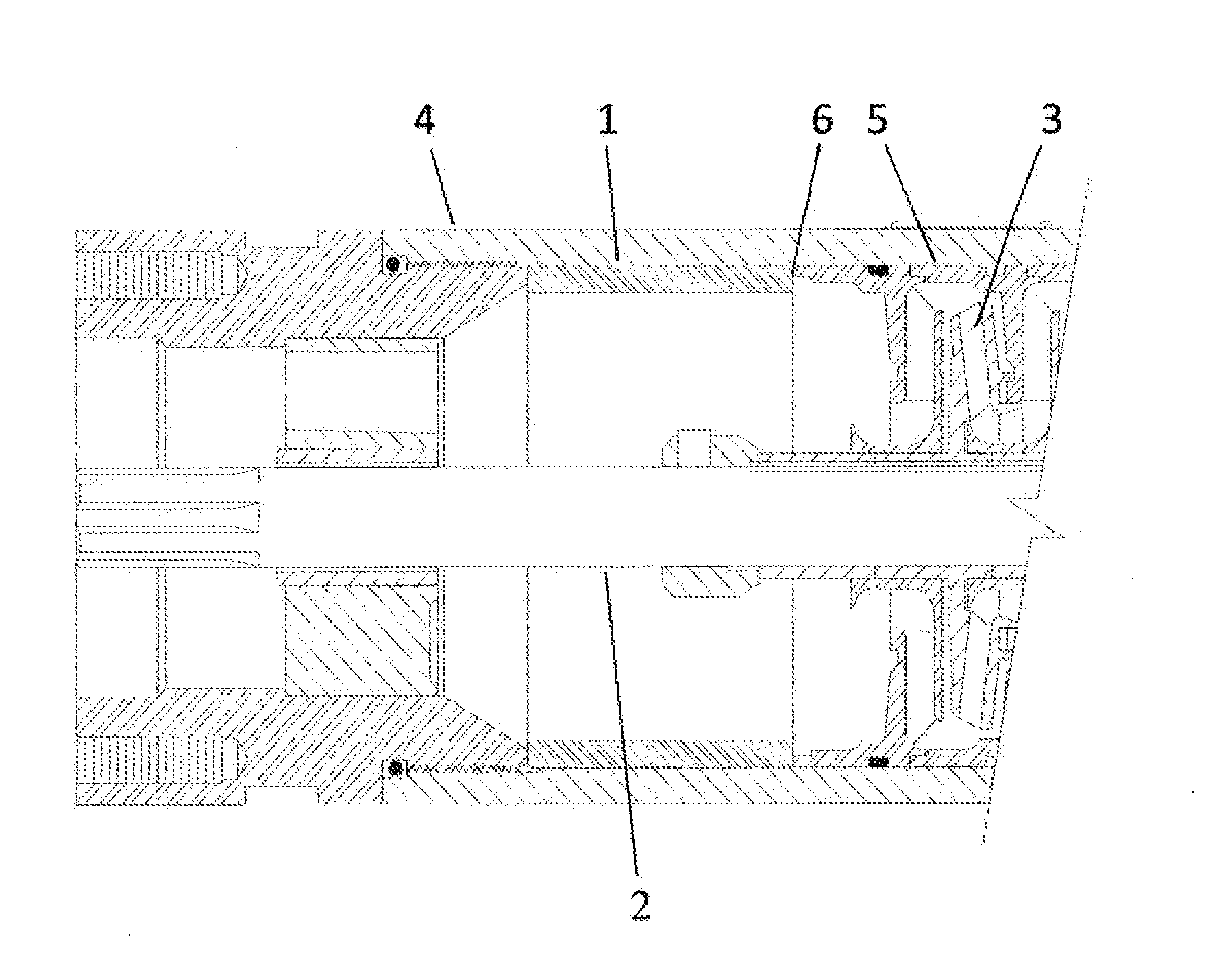
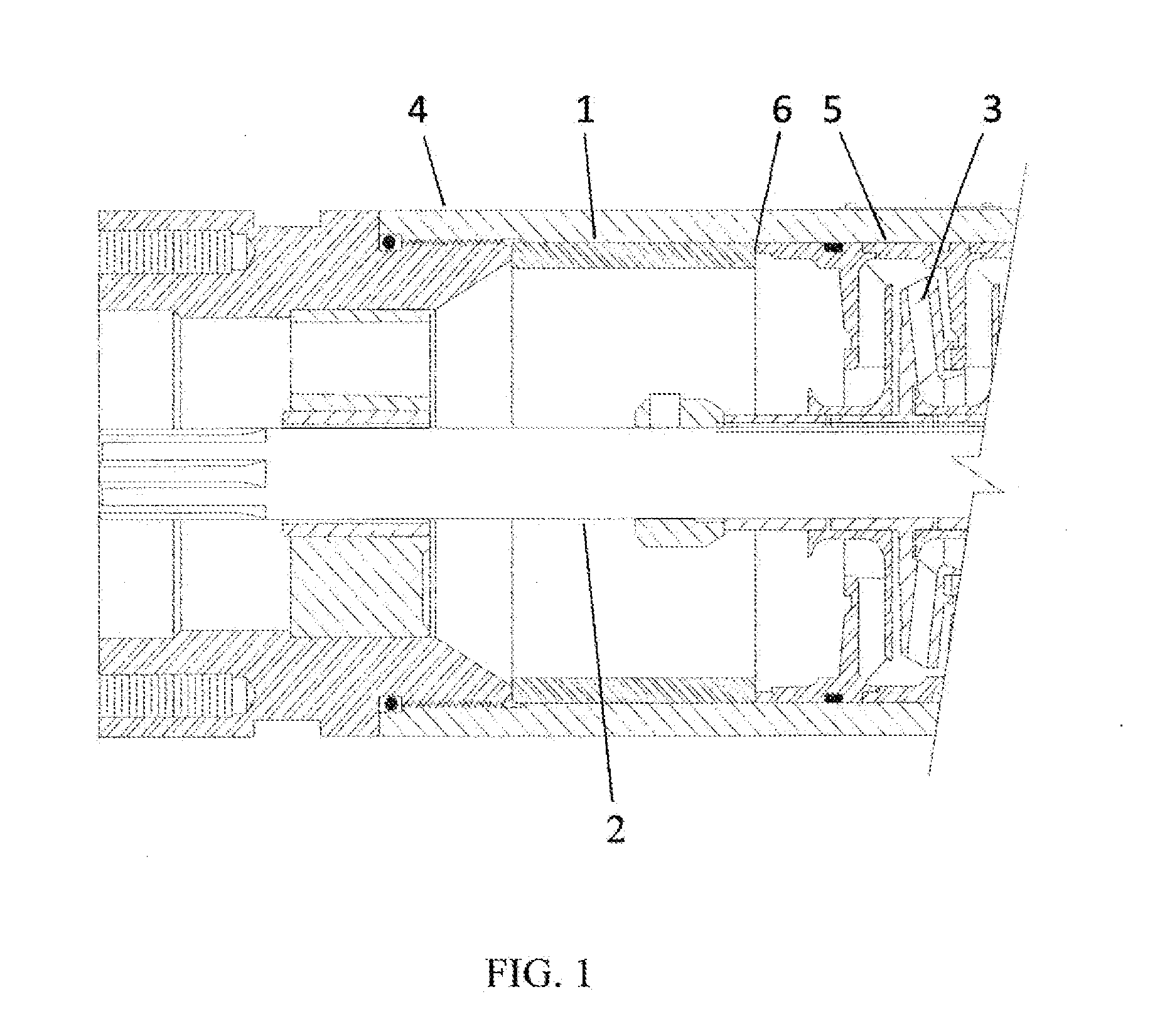
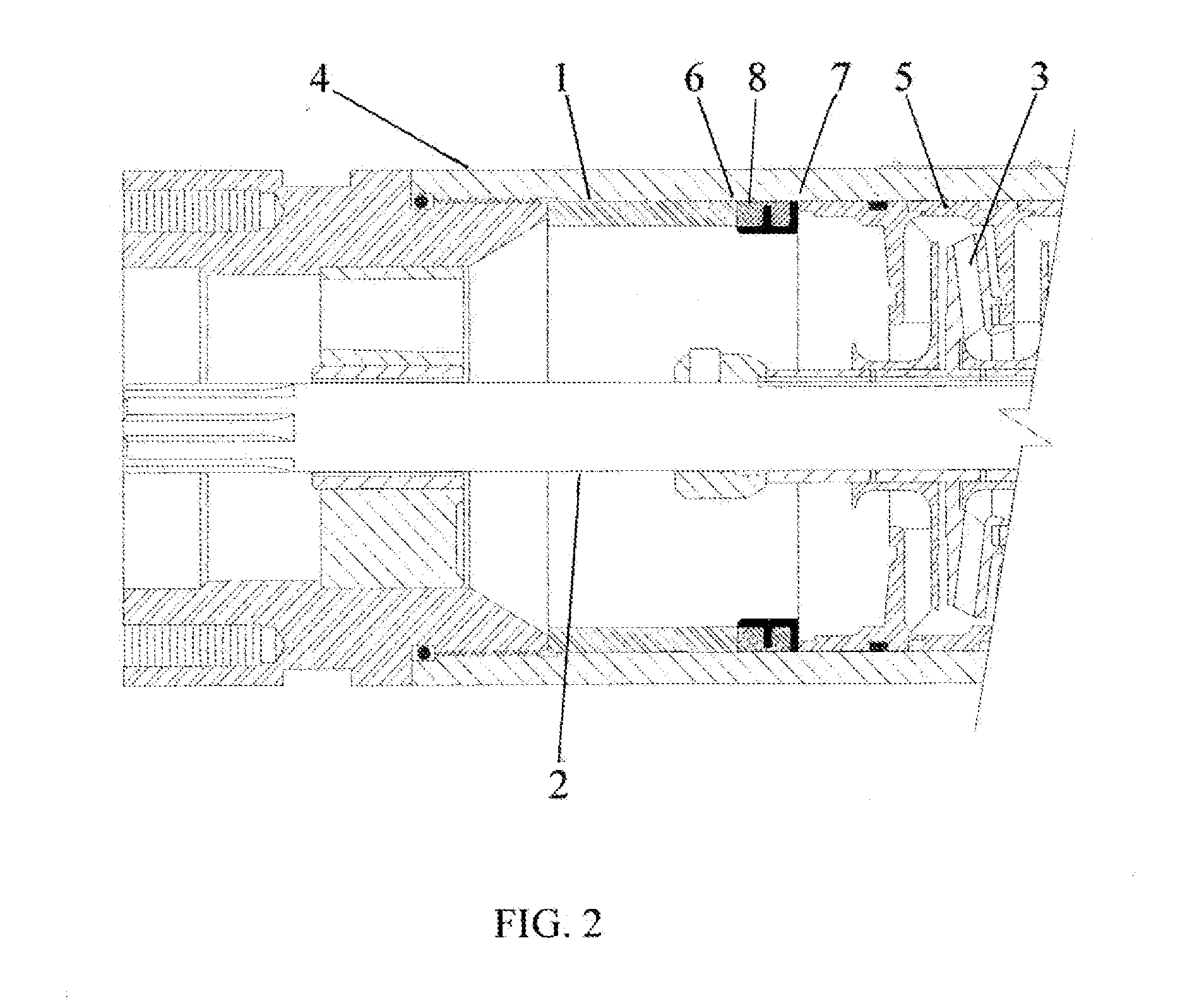
[0013]Given the problems noted in the current technology, some type of dynamic adjustment is needed to provide both constant pressure and pressure relief to the diffuser / impeller stack during pump operation.

[0014]Such a compensator would allow for compression tube 1 short cuts, providing the necessary expandability to adjust for the short cut, and compensate fur long cuts and thermal growth of other pump components with the ability to compress and maintain the pressure desired on the diffuser / impeller stack. Such an arrangement is illustrated in FIG. 2. In the preferred embodiment, the variable compression ring 7, 8 is a ring of hard rubber, plastic, or suitable material (AFLAS, etc.), with a hardness of durometer 90 (an approximate number), where the material 8 provides both compression and elastic properties to accommodate the variation in the compression ring 1 pressure. The new dynamic adjustment is provided structural support with a thin metal insert 7, primarily to provide sta...


PUM


Abstract

A dynamic variable compression ring for use in submersible pumps. where the variable compression ring compensates for metal compression ring measurement errors during assembly. The dynamic variable compression ring also allows for thermal heating of the internal pump components, thus maintaining the desired diffuser compression values.

Description

FIELD OF THE INVENTION[0001]This invention relates to a variable compression methodology to aid in the prevention of diffuser spinning, overheating. and destruction of downhole submersible pumps.BACKGROUND[0002]In current designs, reference FIG. 1 submersible pumps are an assembly of diffusers 5 and impellers 3 contained within the pump housing 4, with a shall 2 powered by an external motor (not shown) to supply the rotational power for the impellers 3 which are keyed to the shaft 2. The impellers 3 provide the lift for the well fluids in order to move the fluids to the surface. The forces associated with the impeller 3 rotation and fluid lift will, at times, cause associated diffusers 5 to rotate inside the housing 4 when they should not. The diffuser 5 rotation generates considerable heat, and can cause housing 4 and / or adjacent stage failures.[0003]To prevent the diffusers 5 from spinning due to the hydraulic reaction of the impellers 3, the diffuser stack, the common reference t...

Claims


Application Information

Patent Timeline
IPC IPC(8): F04B39/00
CPCF04D29/086F04D13/10
Inventor FLOYD, RAYMONDKETTER, CHRISS
Owner FLOYD RAYMOND
Why Eureka
Try Eureka