Display panel and production method thereof

a technology of display panel and production method, which is applied in the field of display panel, can solve the problems of significant deterioration of the characteristics of organic el elements, high active and unstable laminate, and increase and achieve the effect of improving the strength of the bonding between the first substrate and the second substrate, reducing the amount of bubbles remaining inside the glass frit, and increasing the strength of the hermetical seal

Active Publication Date: 2012-11-15
JOLED INC
View PDF8 Cites 94 Cited by
  • Summary
  • Abstract
  • Description
  • Claims
  • Application Information

AI Technical Summary

Benefits of technology

[0014]However, the process of drying and pre-baking by a laser causes abrupt evaporation of the solvent and binder present in the paste, which leads to occurrence of bubbles. Bubbles reduce the surface flatness of glass frit. Therefore, when a sealing substrate is placed face to face with the EL-mounted substrate, the EL-mounted substrate makes partial surface contact, rather than whole surface contact, with the dried and pre-baked glass frit. Welding glass frit that is in partial surface contact with an EL-mounted substrate results in poor bonding between the EL-mounted substrate and the sealing substrate. As a consequence, the mechanical strength of the bonding between the substrates is reduced, along with the reduction in the sealing strength, which accelerates deterioration of organic EL elements.
[0015]In another suggested method, glass frit paste is applied to a sealing substrate and the sealing substrate is placed face to face with the EL-mounted substrate, without removing solvent and binder contained in the paste. That is, the respective substrates are placed face to face while the glass frit remains pasty. In the latter method, after the substrates are placed face to face, the glass frit is locally heated by a laser (laser irradiation for the first time) to remove solvent and binder. Then, the glass frit is again locally heated (laser irradiation for the second time) by the laser adjusted to high power output, thereby joining the EL-mounted substrate and the sealing substrate together. According to the latter method, the substrates are joined together while the glass frit is in pasty liquid phase. Therefore, it is avoided that the glass frit makes partial surface contact with the substrate. Yet, bubbles are still evolved in the glass frit paste at the time of removing solvent and binder with a laser beam, which reduces the density of the glass frit. As a result, the mechanical strength of bonding between the substrates is reduced and the sealing strength is also reduced, which accelerates degradation of the organic EL elements.
[0017]One non-limiting and exemplary embodiment is directed to a display panel having a pair of substrates and a plurality of light-emitting elements disposed between the pair of substrates sealed by glass frit and provides a display panel having excellent durability by improving the sealing strength of the glass frit as well as the mechanical strength.
[0024]Consequently, the strength of bonding between the first substrate and the second substrate is improved, along with the increase in the strength of the hermetical seal of the first substrate and the second substrate, so that a display panel having excellent durability is realized. In addition, since the glass frit is compressed, the width of the glass frit seal is reduced to achieve the effect of narrowing the width of the glass frit.

Problems solved by technology

Generally, materials of such an organic EL laminate are highly active and unstable and therefore easily react with water and oxygen present in the air.
Such a reaction with water and oxygen leads to significant deterioration of the characteristics of organic EL elements.

Method used


Image

  • Display panel and production method thereof
  • Display panel and production method thereof
  • Display panel and production method thereof

Examples


exemplary embodiment 1

Modifications Etc. of Exemplary Embodiment 1

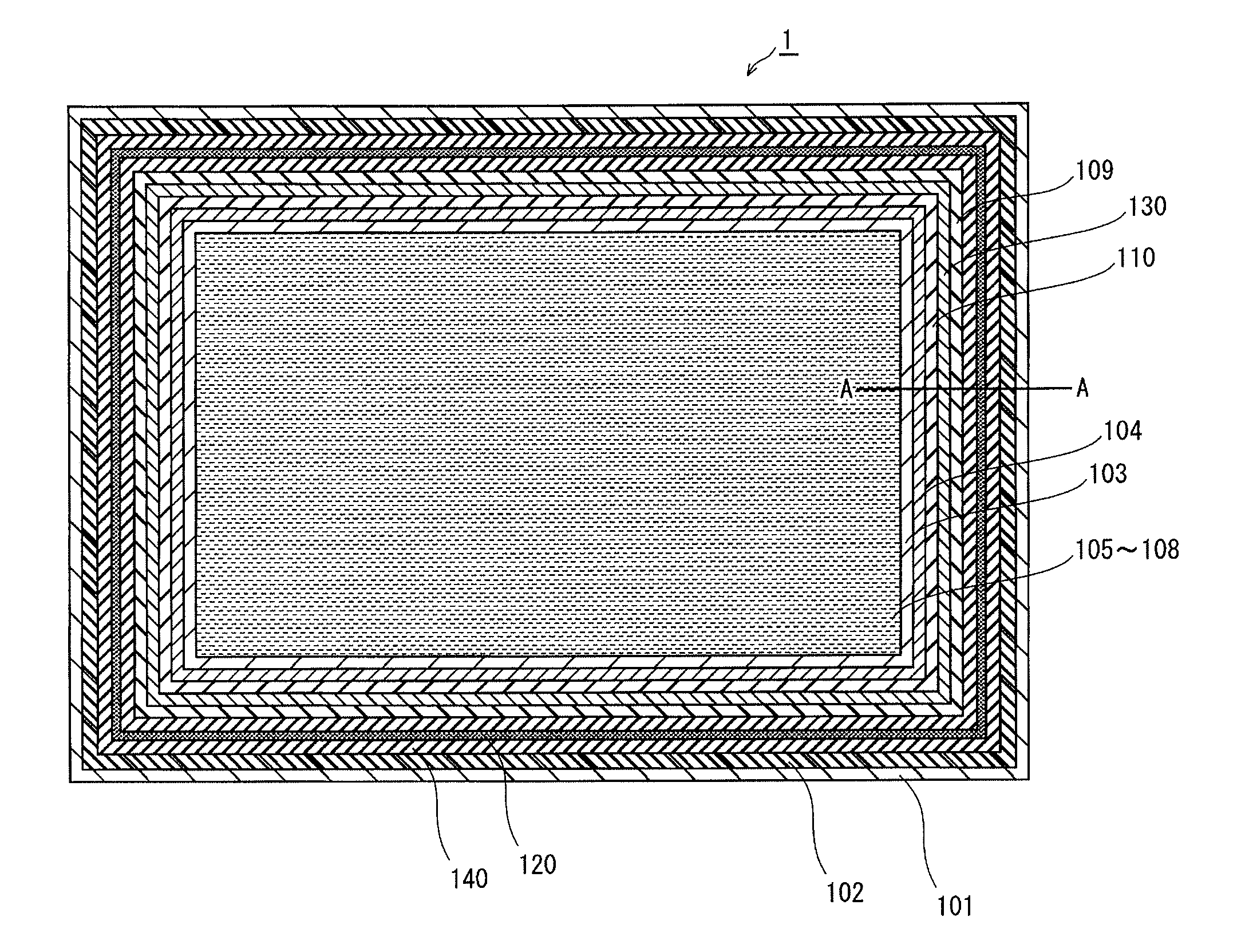
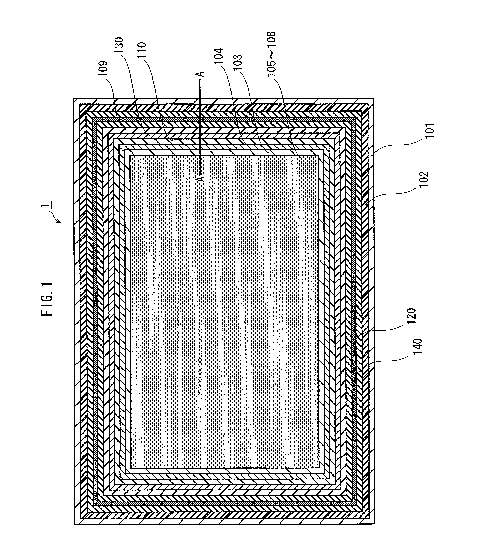
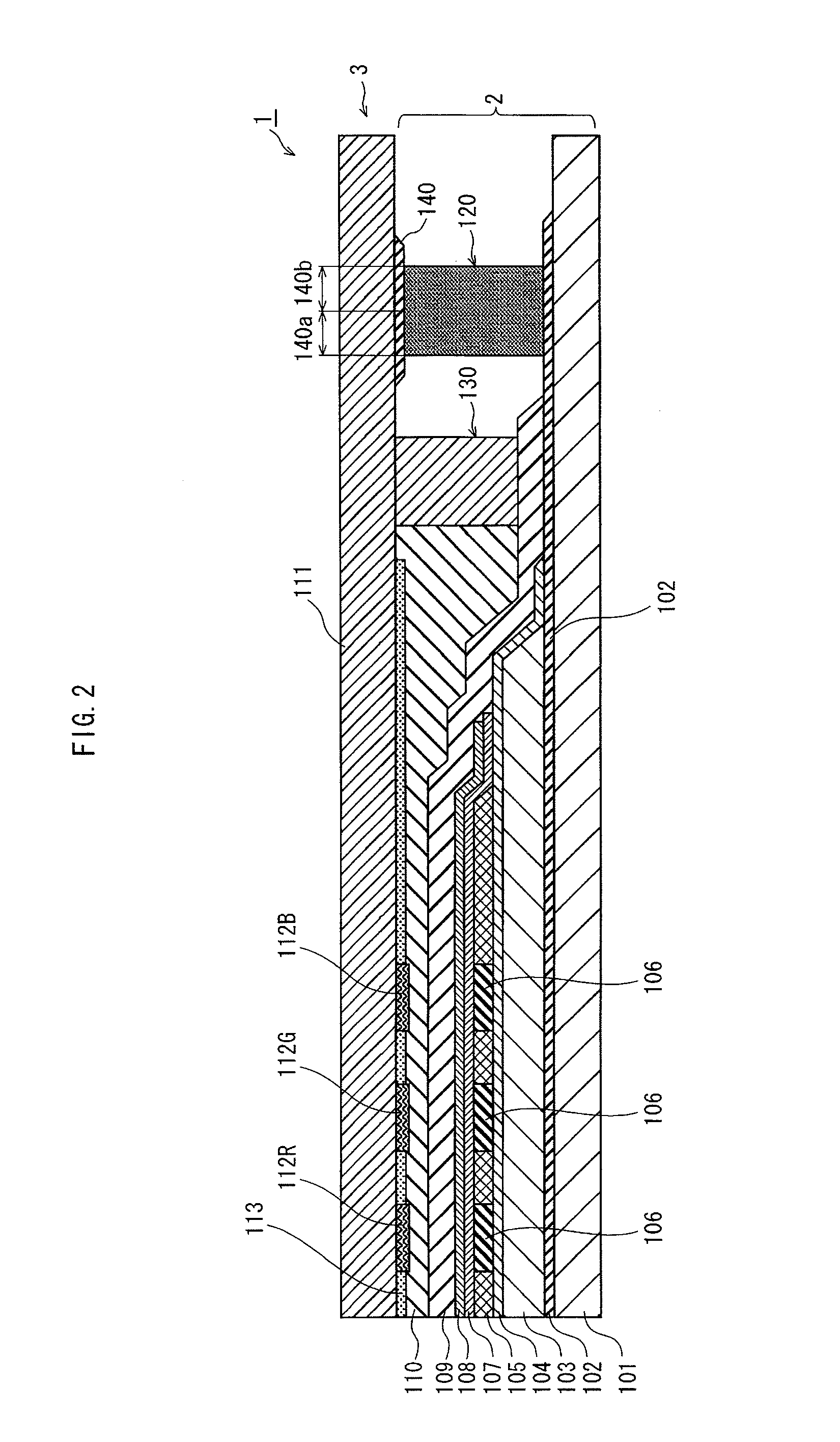
[0220](1) FIG. 9 is a front view of an organic EL display panel 1 according to a modification of the exemplary embodiment 1 of the present disclosure. The structure of the organic EL display panel 1 according to this modification is basically the same as the organic EL display panel 1 according to the exemplary embodiment 1 shown in FIG. 2, except that no thin encapsulating layer 109 is provided on the cathode 108.

[0221]The method for manufacturing the organic EL display panel 1 shown in FIG. 9 is basically the same as the manufacturing method described above, except that the process of forming the thin encapsulating layer 109 is not included.

[0222]Features of the light-shielding part 140 and the resulting effect of increasing the sealing strength of the glass frit part 120 and the bonding strength between the EL substrate 2 and the CF substrate 3 remain the same as described above.

[0223](2) In the exemplary embodiment 1 described above, t...

exemplary embodiment 2

[0237]In the exemplary embodiment 1 described above, the glass frit is subjected to laser irradiation through the light-shielding part 140 in the pre-baking process as well as in the final baking process. In an exemplary embodiment 2, the light-shielding part 140 is not used to cause a temperature gradient in the glass frit. Instead, the spot diameter and path of the laser beam used for irradiating the glass frit is adjusted to cause a temperature gradient in which the temperature of the glass frit is higher in the outer region.

[0238]The structure of the EL substrate 2 and the glass frit paste 120a are similar to that described in the exemplary embodiment 1. The CF substrate 3 is also similar to that described in the exemplary embodiment 1, except that no light-shielding part 140 is provided.

[0239]In the same manner as described in the exemplary embodiment 1, the process of applying glass frit, the process of joining substrates, and the process of UV irradiation and thermal curing a...

exemplary embodiment 3

Modifications Etc. of Exemplary Embodiment 3

[0351](1) FIG. 23 is a front view of an organic EL display panel 1 according to a modification of the exemplary embodiment 3 of the present disclosure. The structure of the organic EL display panel 1 according to this modification is basically the same as the organic EL display panel 1 according to the exemplary embodiment 3 shown in FIG. 17, except that no thin encapsulating layer 109 is provided on the cathode 108.

[0352]The method for manufacturing the organic EL display panel 1 shown in FIG. 23 is basically the same as the manufacturing method shown described above, except that the process of forming the thin encapsulating layer 109 is not included.

[0353]Features of the heat-conducting layer 240 and the resulting effect of increasing the strength of sealing the bonding strength of the EL substrate 2 and the CF substrate 3 by the glass frit part 120 remains the same as described above.

[0354](2) In the exemplary embodiment 3 described abo...


PUM

PropertyMeasurementUnit
thicknessaaaaaaaaaa
viscosityaaaaaaaaaa
diameteraaaaaaaaaa

Abstract

A display panel includes: a first substrate; light-emitting elements on a region of the first substrate; a second substrate facing the first substrate with the light-emitting elements therebetween; a glass frit between the first substrate and the second substrate so as to surround the region of the first substrate in which the light-emitting elements are disposed, the glass frit providing a hermetic seal between the first substrate and the second substrate; and a light-shielding part formed on one of the first substrate and the second substrate so as to extend along the glass frit, the light-shielding part shielding light. The light-shielding part has a lower light-shielding property in a region corresponding to the outer region of the glass frit than in a region corresponding to the inner region of the glass frit. The glass frit has been irradiated with light through the light-shielding part.

Description

CROSS REFERENCE TO RELATED APPLICATION[0001]This is a continuation application of PCT Application No. PCT / JP2011 / 004074 filed Jul. 19, 2011, designating the United States of America, the disclosure of which, including the specification, drawings and claims, is incorporated herein by reference in its entirety.TECHNICAL FIELD[0002]The present disclosure relates to a display panel in which a sealing substrate and a substrate having light-emitting elements thereon are sealed together using glass frit. The present disclosure also relates to a manufacturing method for such a display panel.DESCRIPTION OF THE RELATED ART[0003]Examples of display panels having light-emitting elements of a self-emission type include organic electroluminescence (EL) display panels, plasma display panels (PDP), and field emission displays (FED). Such display panels offer various advantages: not requiring a backlight; providing a wide viewing angle; being slim and suitable for power saving; having quick response...

Claims


Application Information

Patent Timeline
Patent Type & Authority Applications(United States)
IPC IPC(8): G09G3/30B32B37/06B32B37/12
CPCH01L27/3272H01L51/5246H10K59/126H10K50/8426H05B33/04
Inventor MASUDA, HIROYUKI
Owner JOLED INC
Why Eureka
Try Eureka