Display device with optical sensors

a display device and optical sensor technology, applied in the field of display devices, can solve the problem of higher power consumption of display devices with optical sensors than display devices without optical sensors, and achieve the effect of reducing the power consumption of display devices, accurate distinction from noise, and reducing the influence of changes

Inactive Publication Date: 2012-11-15
SHARP KK
View PDF4 Cites 22 Cited by
  • Summary
  • Abstract
  • Description
  • Claims
  • Application Information

AI Technical Summary

Benefits of technology

[0034]According to the first or ninth aspect of the present invention, it is determined whether the mode is normal or standby, and the recognition processing portion is stopped from operating in the standby mode, thereby reducing power consumption of the display device. Moreover, when the comparison image based on signals being read from the optical sensors changes to a predetermined degree corresponding to the ambient luminance, or more than the predetermined degree, after transition to the standby mode, the mode transitions to normal. As a result, the transition to the normal mode can take place before a sensing target touches the screen. Accordingly, a touch position can be promptly detected after a quick exit from the standby mode, and an accurate distinction from noise can be made by a determination according to the ambient luminance, so that the standby mode can be prevented from being or not being cancelled by mistake. Thus, the standby mode can be correctly exited.
[0035]According to the second aspect of the present invention, the stored comparison image and the new comparison image are compared pixel by pixel, and transition to the normal mode takes place when the number of pixels whose difference in pixel values is greater than or equal to the first threshold is greater than or equal to the second threshold, so that the transition to the normal mode can take place before a sensing target touches the screen. Thus, a touch position can be promptly detected after a quick exit from the standby mode.
[0036]According to the third aspect of the present invention, at least one of the first and second thresholds is determined in accordance with the ambient luminance, and therefore, by determining at least one of the first and second thresholds so as to avoid or reduce the influence of a change in the ambient luminance, it is rendered possible to accurately determine whether or not to cancel the standby mode.
[0037]According to the fourth aspect of the present invention, at least one of the first and second thresholds is determined so as to monotonically increase relative to the ambient luminance, and therefore, for example, when the ambient luminance is low, the first threshold is set low, so that a change in a new comparison image can be distinguished from noise and even a slight change can be accurately detected, thereby preventing the standby mode from not being cancelled by the erroneous determination that there is no change. Moreover, when the ambient luminance is high, the first threshold is set high, thereby avoiding erroneous determination due to a slight change in pixel values caused by noise or suchlike, so that a change in the new comparison image can be accurately detected. Furthermore, when the ambient luminance is low, the second threshold is set low, so that a change in the new comparison image can be accurately detected on the basis of a small number of pixels whose pixel values have changed. Further still, when the ambient luminance is high, the second threshold is set high, thereby preventing the standby mode from being erroneously cancelled by mistaking a change in the new comparison image due to increased noise for a change in an image of the sensing target. Thus, a touch position can be promptly detected after a correct exit from the standby mode.
[0038]According to the fifth aspect of the present invention, the infrared backlight is turned off or dimmed in the standby mode, so that power consumption of the display device can be reduced.
[0039]According to the sixth aspect of the present invention, the mode determination process is performed using the comparison image having a smaller number of pixels than the recognition target image, so that the size of memory and the amount of computation required for the mode determination process can be reduced.

Problems solved by technology

Consequently, the display device with optical sensors has a problem of its power consumption being higher than display devices without optical sensors.

Method used


Image

  • Display device with optical sensors
  • Display device with optical sensors
  • Display device with optical sensors

Examples


Embodiment Construction

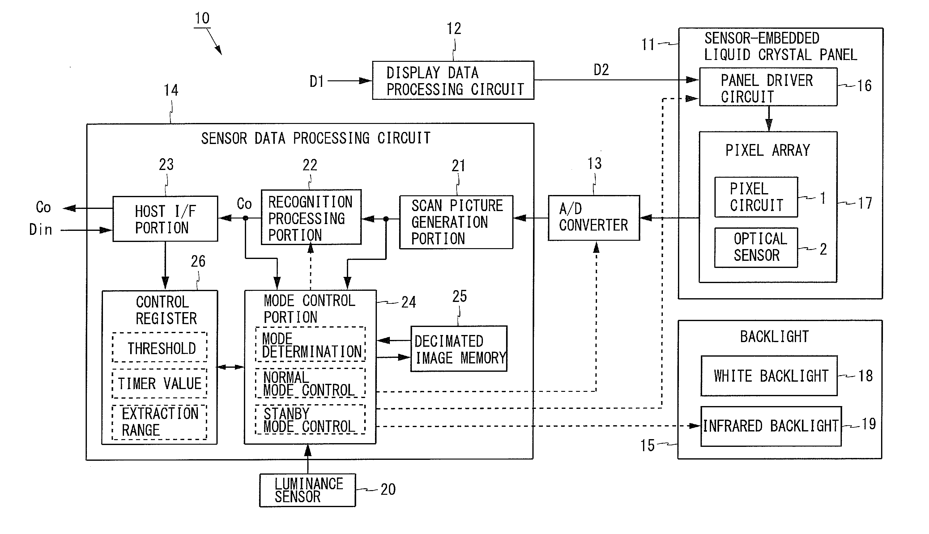
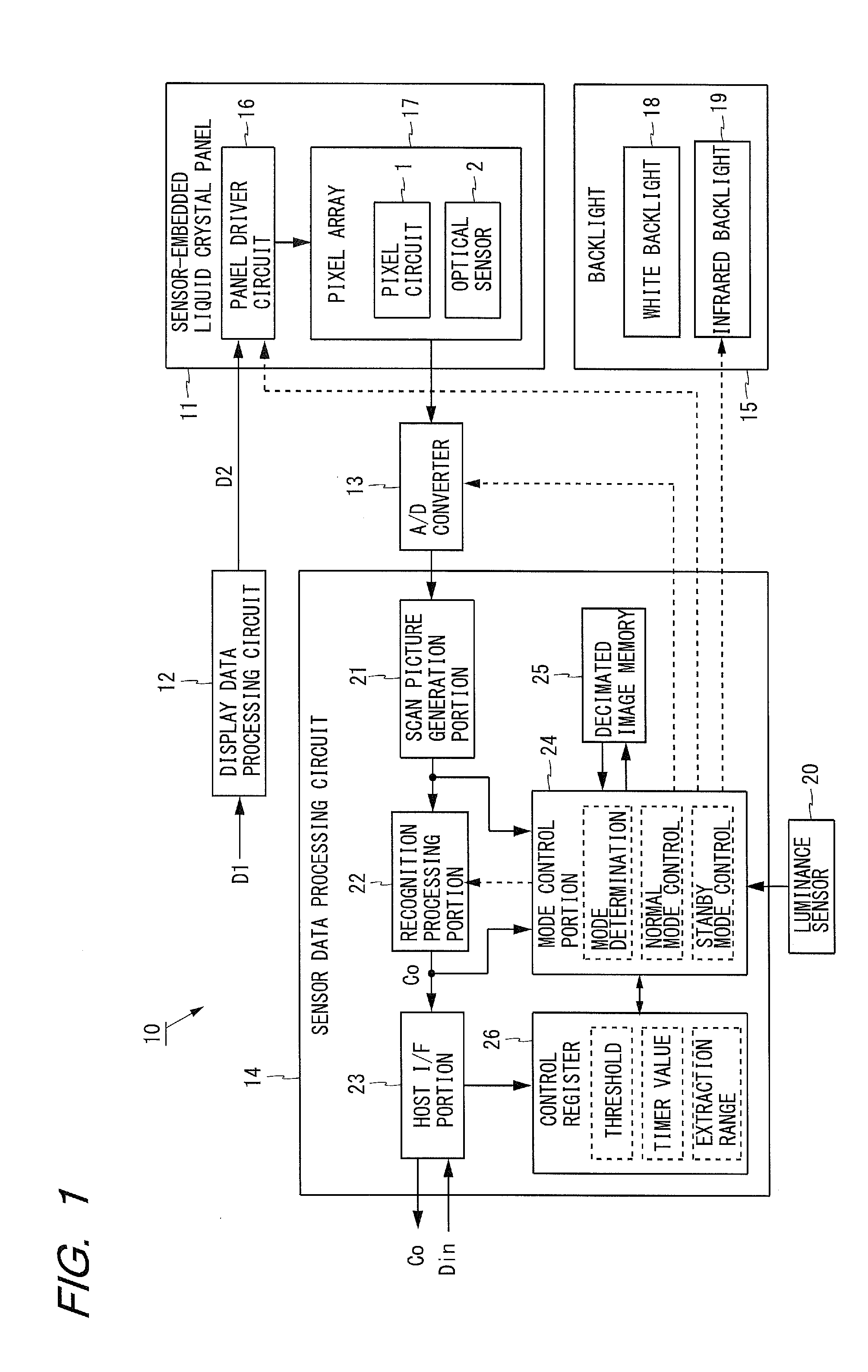
[0054]FIG. 1 is a block diagram illustrating the configuration of a liquid crystal display device according to an embodiment of the present invention. The liquid crystal display device 10 shown in FIG. 1 is provided with a sensor-embedded liquid crystal panel 11 (hereinafter, simply referred to as a liquid crystal panel), a display data processing circuit 12, an A / D converter 13, a sensor data processing circuit 14, a backlight 15, and a luminance sensor 20. The liquid crystal panel 11 includes a panel driver circuit 16 and a pixel array 17. The pixel array 17 has a plurality of pixel circuits 1 and a plurality of optical sensors 2 arranged two-dimensionally.

[0055]The liquid crystal display device 10 externally receives display data D1. The display data processing circuit 12 performs as necessary color correction processing, frame-rate conversion processing, or the like, on the display data D1, and outputs display data D2. The panel driver circuit 16 writes voltages, which correspon...


PUM


Abstract

In a display device with optical sensors, a recognition processing portion (22) performs recognition processing on a scan picture generated by optical sensors (2), and calculates a position. A mode control portion (24) determines whether or not the mode is standby so that the recognition processing portion (22) is stopped from operating. At the time of transition to the standby mode, decimated image memory (25) stores a decimated image with a decreased number of pixels. The mode control portion (24) performs pixel-by-pixel comparison between the stored decimated image and a decimated image supplied anew, and exits the standby mode when the number of pixels whose difference in pixel values is greater than or equal to a first threshold is greater than or equal to a second threshold. Here, the first and second thresholds are appropriately set in accordance with an ambient luminance L from a luminance sensor (20), and therefore, any change in the image can be accurately distinguished from noise, thereby preventing the standby mode from being or not being cancelled by mistake.

Description

TECHNICAL FIELD[0001]The present invention relates to display devices, particularly to a display device having a plurality of optical sensors provided on a display panel.BACKGROUND ART[0002]Recent years have seen widespread use of electronic equipment which can be operable by touching its screen with a finger, a pen, or the like. In a known method for detecting a touch position in a display screen, a plurality of optical sensors are provided on a display panel and used to sense a projected or reflected image formed by a finger or suchlike approaching the screen. In another known method, to detect a touch position with high accuracy for any display data, a display device is provided with an infrared backlight for emitting infrared light, and a reflected image formed by infrared light is sensed using optical sensors.[0003]In addition to the infrared backlight, such a display device with optical sensors is provided with, for example, an A / D converter for converting signals being read f...

Claims


Application Information

Patent Timeline
Patent Type & Authority Applications(United States)
IPC IPC(8): G06F3/038
CPCG02F1/13338G06F3/0412G09G2360/145G09G2360/144G09G2330/022G06F3/04164G06F3/04184G06F3/042
Inventor GOTOH, TOSHIMITSUOKADA, ATSUSHI
Owner SHARP KK
Why Eureka
Try Eureka