Air propeller arrangement and aircraft

Inactive Publication Date: 2012-11-15
GKN AEROSPACE SWEDEN AB
View PDF7 Cites 20 Cited by
  • Summary
  • Abstract
  • Description
  • Claims
  • Application Information

AI Technical Summary

Benefits of technology

[0012]For a box-shaped, interconnected blade pair (i.e. where the distance between the root ends and the tip ends is about the same) the reduction of induced drag can be expected to be more significant than in the case where the inter-connected blades form a triangle with the tip ends close together.
[0013]However, a triangular or triangular-like shape can give a lower root bending moment and tip displacement compared to inter-connected blades forming a box-shape. Various hybrid combinations of triangular- and box-shape are conceivable. What shape to use depends on the application. A shape that is advantageous in many situations is a generally triangular shaped structure that has a certain gap between the blades at their tip ends.
[0014]Based on experience of aircraft wings, which have a shape in many ways sim

Problems solved by technology

This results in very high propulsive efficiencies.
A conventional un-swept propeller, i.e. a propeller where the propeller blades extend substantially perpendicular to the propeller axis, is limited by the forward speed of the airplane, since the combination of the propeller rotational speed and airplane forward speed results in high relative Mach numbers at the propeller blade tips which cause

Method used


Image

  • Air propeller arrangement and aircraft
  • Air propeller arrangement and aircraft
  • Air propeller arrangement and aircraft

Examples


Example

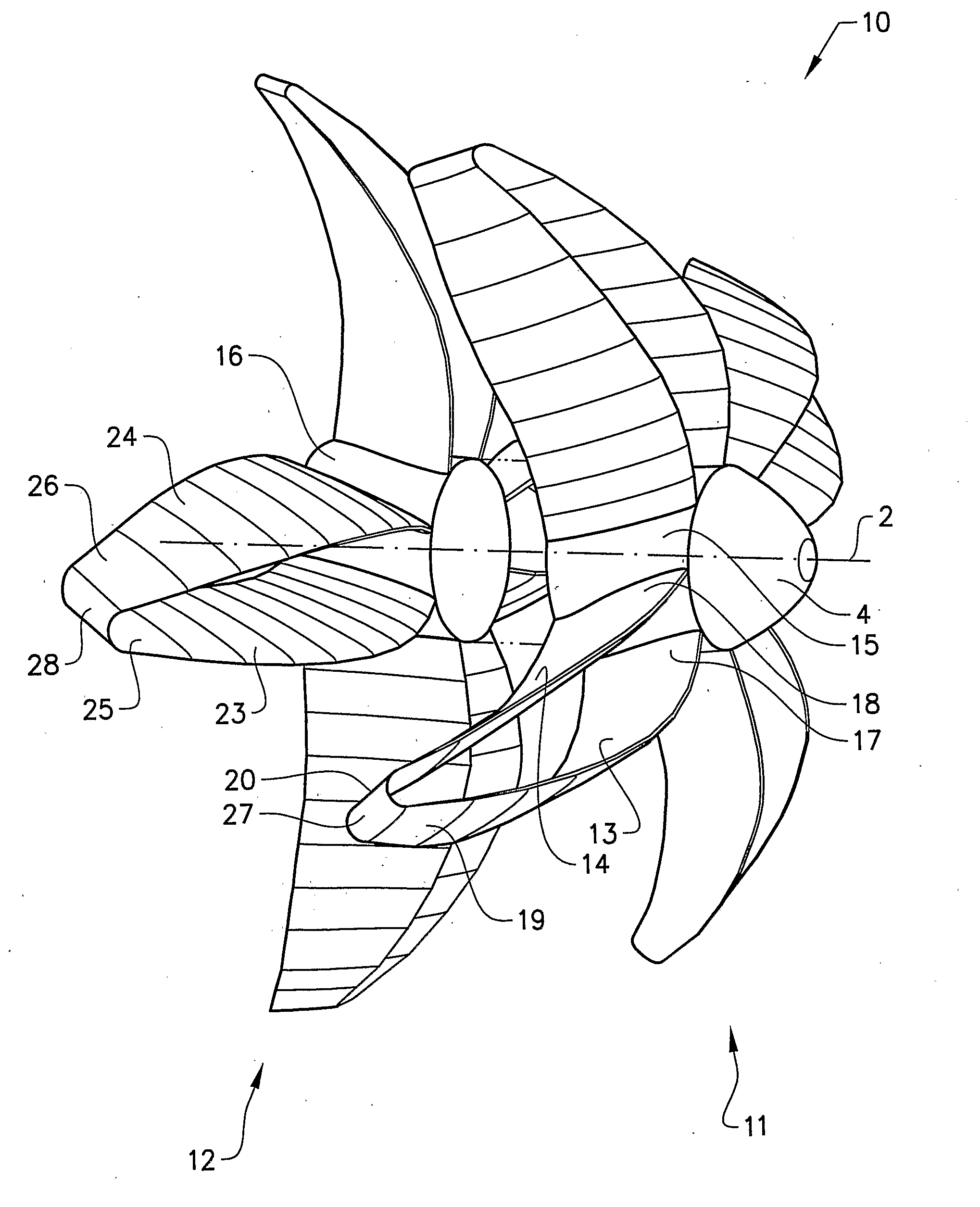
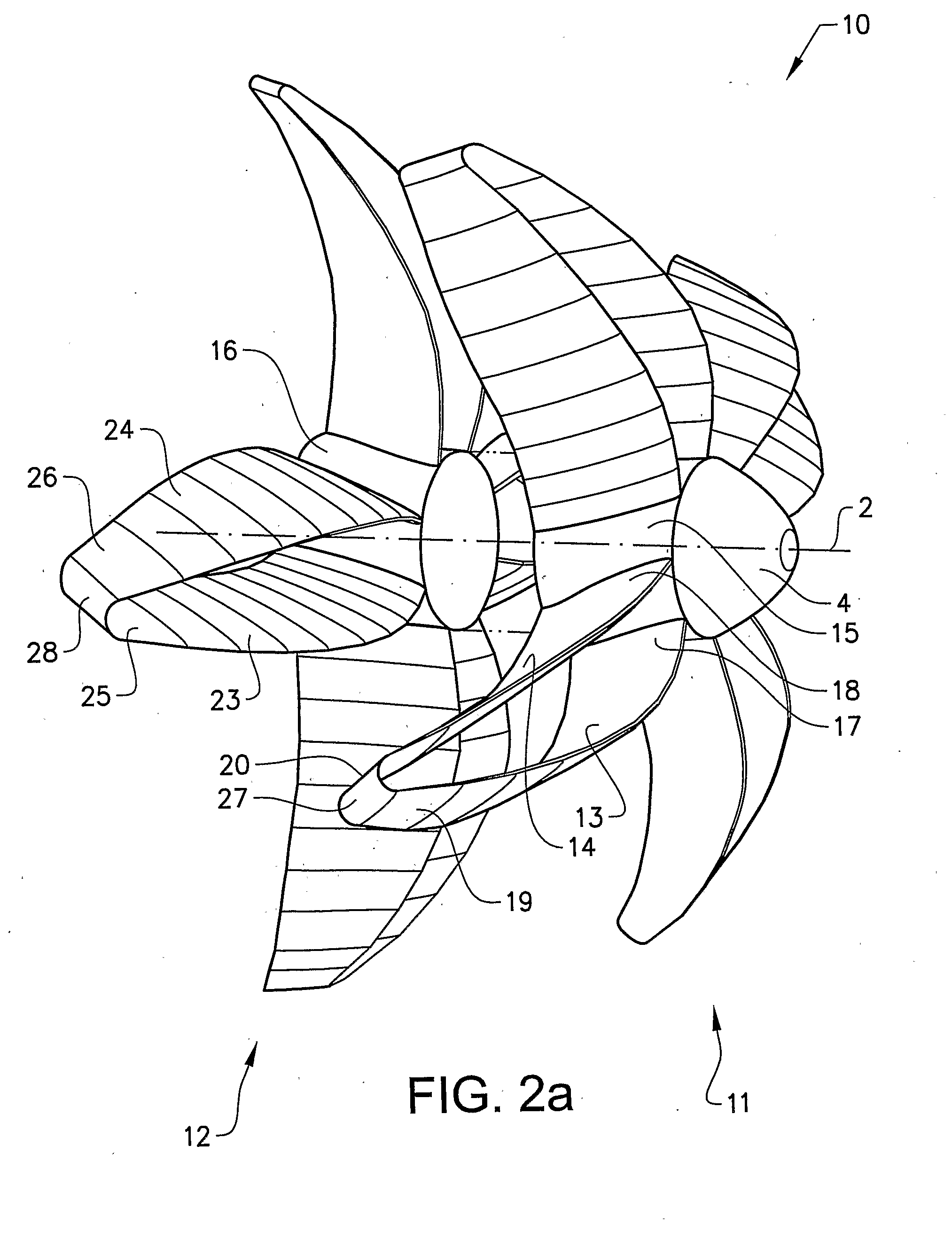
[0037]Conventionally, each propeller blade discussed here has an airfoil shape with a leading edge, a trailing edge, a suction side and a pressure side. The term chord refers to the imaginary straight line joining the trailing edge and the center of curvature of the leading edge. The term chord length (c) is the distance between the trailing edge and the point on the leading edge where the chord intersects the leading edge, and is thus a measure of the width of the blade. Further, each blade has a root (inner) end arranged at the hub member and a tip (outer) end positioned at a distance from the hub member as seen in a radial direction of the hub member. Commonly, the chord length varies along the blade with a greater length at the root end and a smaller length at the tip end.

[0038]Below it is referred to 0.25c and 0.5c; these terms refer to an imaginary line. drawn between the points representing 25% and 50%, respectively, of the length of the chord line along the blade profile as ...


PUM


Abstract

An air propeller arrangement for propulsion of a fixed-wing aircraft includes a first air propeller that includes a first hub member and at least a first and a second propeller blade, the first and second blades being configured to contribute significantly to the propulsion and having a substantially equal length. Each of the blades has an inner, root end arranged at the first hub member and an outer, tip end positioned at a distance from the first hub member such that each blade extends in a radial direction from the first hub member. The first and second blades are interconnected at their outer ends. An aircraft provided with such an air propeller arrangement is also provided.

Description

BACKGROUND AND SUMMARY[0001]This invention relates to an air propeller arrangement for propulsion of a fixed-wing aircraft. In particular, the invention relates to high speed propellers. The invention also relates to an aircraft provided with such an air propeller arrangement.[0002]Strict environmental goals on reducing emissions of carbon dioxide, nitrogen oxides and noise for the aviation sector have enhanced the need for further development of aircraft propulsion systems.[0003]Propellers have been used for propulsion of fixed-wing aircrafts since the Wright brothers first flew their Wright Flyer in 903, but since the high speed jet engine technology was introduced on the commercial air transport market in the 1950s propellers have mostly been used for commuter transport, general aviation and freighters. Accordingly, development of aircraft engines has been focused on jet engines.[0004]Propellers in general are generating very low excess kinetic energies due to very low operating ...

Claims


Application Information

Patent Timeline
IPC IPC(8): B64C11/16
CPCB64C11/18Y02T50/64B64D2027/026B64C11/48B63H1/265Y02T50/60
Inventor AVELLAN, RICHARDLUNDBLADH, ANDERS
Owner GKN AEROSPACE SWEDEN AB
Why Eureka
Try Eureka