Cranial plating and bur hole cover system and methods of use

a technology of cranial surface and bur hole cover, which is applied in the field of cranial closure improvements, can solve the problems of palpable and often visible protrusions, gross external deformation, and distressing patient's accompanying discomfort from rubbing, so as to minimize the cranial surface profile, improve the effect of cranial closure, and reduce the protrusions

Inactive Publication Date: 2012-11-15
OSTEOMED
View PDF18 Cites 22 Cited by
  • Summary
  • Abstract
  • Description
  • Claims
  • Application Information

AI Technical Summary

Benefits of technology

[0007]The present disclosure generally comprises a cranial closure system, devices and methods of use, tooling and kits for improving cranial closure outcomes by using a device including a cranial plate or a bur hole cover with a minimized cranial surface profile. The devices are substantially inset within the kerf and / or bur hole and thus reduces protrusions on the cranial surface and thus provides a better clinical outcome for the patient. Additional embodiments further reduce cranial protrusions by partially or fully insetting the device in relation to the outer surface of the cranium.
[0010]Yet another embodiment of the present invention features a specialized tooling apparatus to create a more precise impression for the placement of the attachment wings of an embodied cranial plating and / or bur hole cover device. The tooling apparatus is made to attach to standard neurosurgical tooling. And a preferred tooling apparatus includes a drill bit attachment and guard mechanism. The drill bit attachment comprises a shaft, cutting head and cylindrical tip for creating a pilot hole. The guard attachment fits over the shaft of the drill bit and the top attaches to the drill the guard prevents the drill from drilling past a certain preset depth. Additionally, the guard comprises protruding posts or an orientation ridge which fit against the bone edge so the cylindrical tip makes the pilot hole a standard distance from the edge of the craniotomy and the cutting head removes a more precise section of bone near the kerf.
[0011]Additional embodiments feature methods of using the embodied cranial plating device, one embodied method places the keel portion of the plating device within the kerf and affixes the attachment wings of the device on the outer cranial surface without making an impression in the bone first. An additional embodiment uses readily available neurosurgery tools and with a free-hand technique a perforator or bur hole creator is used to cut away a section of bone to create an impression to place the wings of the cranial plate into the impression and to reduce the cranial profile of the plate on the outer surface of the cranium. Another additional embodiment utilizes an embodied precision tooling apparatus to create precise impressions in depth and orientation to the kerf, and affixation pilot holes to secure an embodied cranial plating device to the cranium resulting in a reduced cranial profile that may allow the entire plating system to be fully inset into the cranium and thus avoiding or minimizing the protrusions typically associated with cranial plate devices.

Problems solved by technology

Current cranial plates, bur hole covers and screw systems are mainly if not entirely affixed on the outer surface of the cranium resulting in palpable and often visible protrusions which provide discomfort if in a place where the scalp moves against the protrusions regularly.
Because many craniotomies are performed below the hairline, this often results in gross external deformity.
Even for craniotomies located off of the forehead, the palpable or visible deformity (particularly for patients who do not have covering hair) and / or accompanying discomfort from the rubbing is often distressing to the patient.
Unfortunately, a suitable device for assisting cranial reconstruction and decreasing cranial deformities and discomfort has not yet been described.

Method used


Image

  • Cranial plating and bur hole cover system and methods of use
  • Cranial plating and bur hole cover system and methods of use
  • Cranial plating and bur hole cover system and methods of use

Examples


example 1

Cranial Plating Device Design Variations

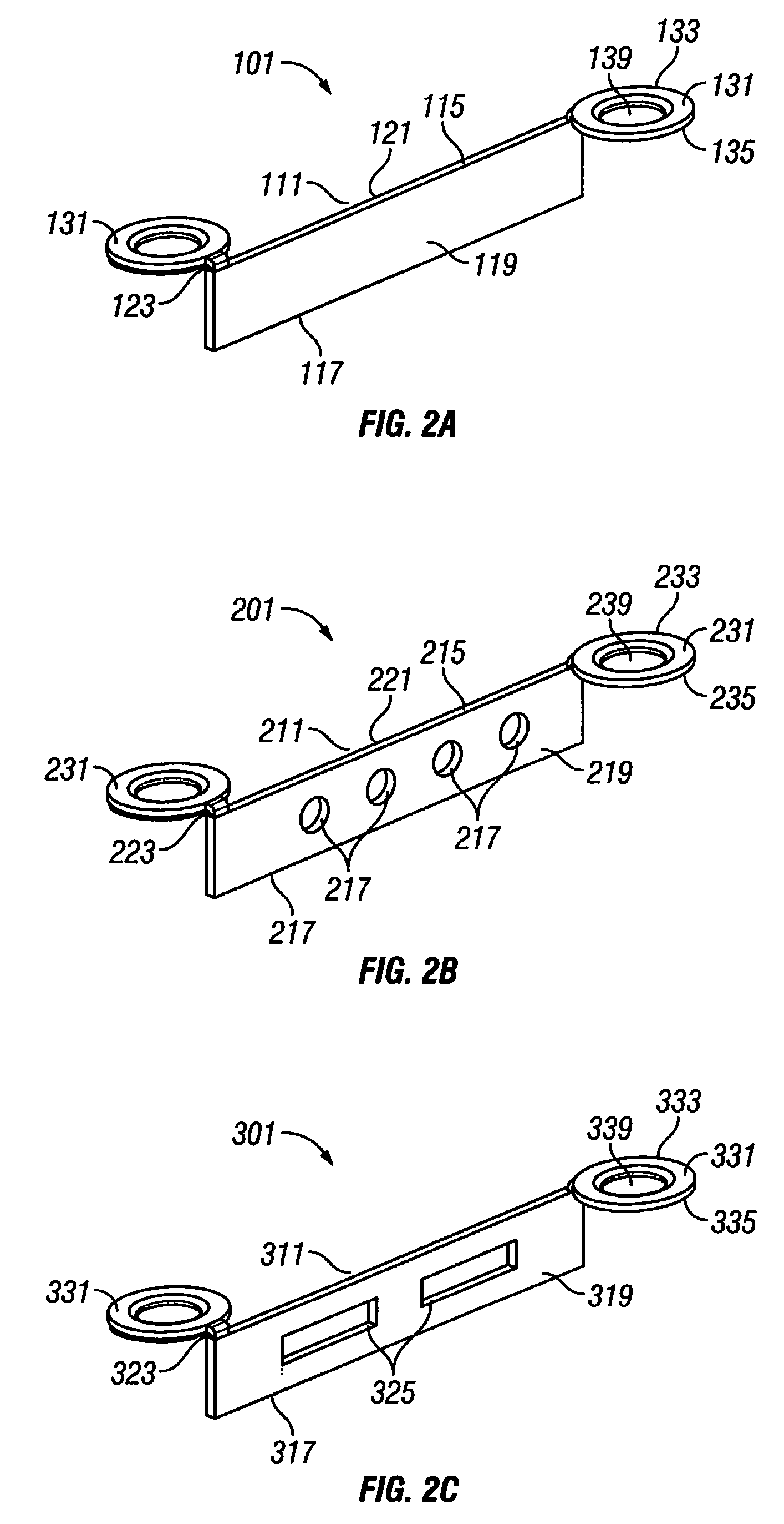
[0072]The kerf cranial closure device contemplated will feature many of the following properties which may optimize cranial closure performance:

[0073]1) The design is intended to specifically close the bony defect made in the skull by any of the common commercially available craniotomes, known as the kerf;

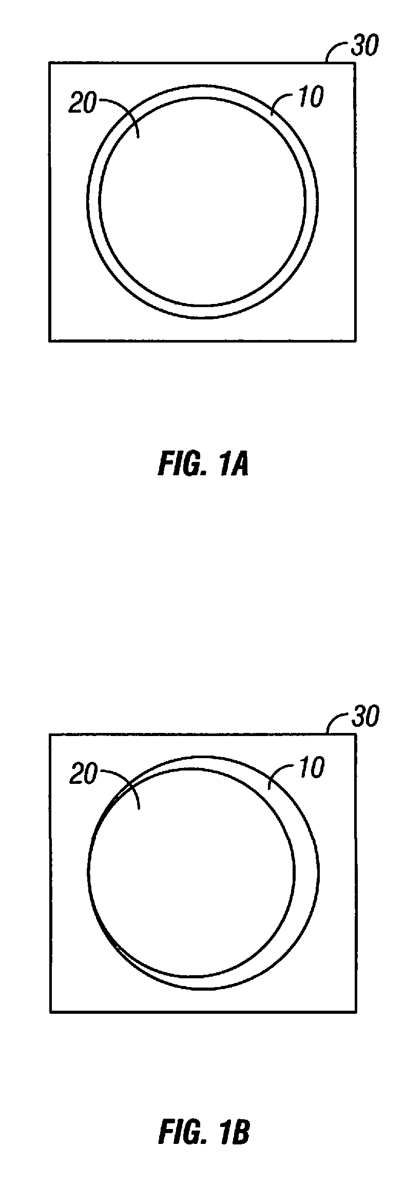
[0074]2) The keel portion of the cranial plate shall reside within the kerf;

[0075]3) The cranial plate fixation wings shall be on opposing sides of each other in relation to the keel;

[0076]4) The cranial plate fixation wings shall have a tapered fixation aperture which allows for the placement of a tapered fixation screw to reside flush within the cranial plate wing and allows for the thread of the fixation screw to secure into the cranium and flap;

[0077]5) The keel portion should be flexible or bendable, and / or manufactured with specific angles or curves to allow for the variability for closing various kerf configurations;

[0078]6) The keel p...

example 2

Tooling Embodiments

[0080]The tooling system may comprise of an impression device which is a high-powered drill which consists of the cylindrical or disc-like bur (drill-bit) and the surrounding guide, the drill-bit is meant to be applied end on into the bone to make semicircular depression in the bone comprising a ⅗ to almost one whole circle that has a central point to allow the bit to bite bone at a precise spot this will also serve to create a pilot hole for screw when the plate is applied.

[0081]Another embodiment of the tooling system comprises the use of a guide the guide covers all the drill-bit except the last 0.4 to 0.7 mm the disc section the guide will prevent the drill-bit from cutting too deep when the guide tip rests on the bone, the impression made is at the proper depth to receive the plate. The guide has a two orientation posts or an orientation ridge, that are rested at the edge of the bone to assure that the impressions made at the edge of the bone are at the prope...

example 3

Exemplary Method of Using an Embodied Cranial Plating System
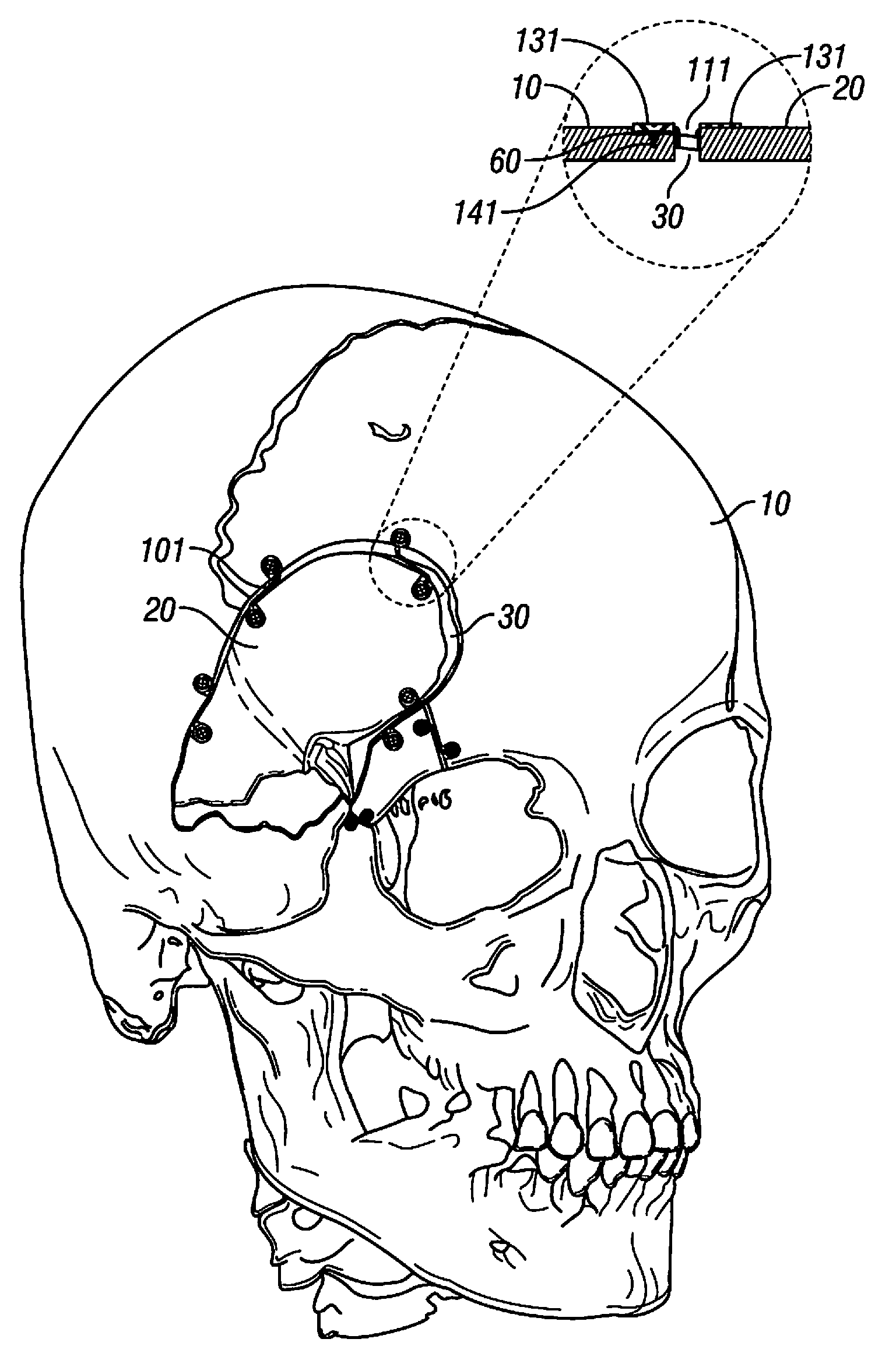
Cranial Defect

[0082]In the creation of a craniotomy, the bone is opened from its external surface to the level of the dura by placement of one or more bur holes, made either freehand with a high-speed drill or with a cranial perforator. The bur holes are connected with a high speed drill router (craniotome footplate attachment), which creates a trough in the bone, known as the kerf.

Closure of Cranium

[0083]At the conclusion of the intracranial part of the operation, the free bone flap is typically secured to the surrounding cranium with a fixation device in which pilot holes are drilled in the cranial flap and a plurality of fixation devices are attached to the cranial flap with screws inserted into the pilot holes, then the cranial flap is placed back into the cranial opening, and positions for attachment of the fixation devices is measured and marked with an awl, and a pilot hole is drilled into the cranium and the fixatio...


PUM


Abstract

The present disclosure is for a device, tooling, methods of use and kits containing the cranial plates and bur hole covers used for resecuring a cranial flap after a craniotomy. The cranial repair system is meant to reduce the profile of cranial plates or bur hole covers on the external surface of the cranium after a craniotomy is performed. The embodied devices of present disclosure are designed to reside substantially within the kerf or bur holes and thus minimize the surface area of devices resides on the external surface of the cranium. Additional embodiments include kits, tooling and methods to further reduce and / or eliminate the external profile of the cranial plate on the external cranial surface.

Description

CROSS REFERENCE TO RELATED APPLICATION(S)[0001]This application claims the benefit of priority under 35 U.S.C. §119(e) of U.S. Ser. No. 61 / 484,641 filed May 10, 2011 the entire content is incorporated herein by reference.BACKGROUND OF THE INVENTION[0002]1. Field of the Invention[0003]The invention relates generally to cranial closure improvements and more specifically to devices and methods used to improve cranial healing and reconstruction and the decrease in patient discomfort and / or palpable or visible deformities often present after a craniotomy.[0004]2. Background Information[0005]Craniotomy is a common operation in the United States. It is performed for a variety of indications, including head trauma, aneurysm repair, and tumor removal, among others. Most craniotomies are performed by drilling one or more bur holes in the skull down to the level of the dura covering the brain and connecting them with a routing bit on a high-speed drill. The bit pulverizes a tract of bone typic...

Claims


Application Information

Patent Timeline
Patent Type & Authority Applications(United States)
IPC IPC(8): A61B17/80A61B17/16A61B17/88
CPCA61B17/688A61B17/1695A61B17/8061A61B17/8085
Inventor NAKAJI, PETER
Owner OSTEOMED
Why Eureka
Try Eureka