Joint Resurfacing Prosthetic Implant System

a prosthetic implant and joint technology, applied in the field of prosthetic implants, can solve the problems of reducing the functionality of the joint, limiting the viability of the joint, and additional surgical procedures, and achieve the effect of economic production and avoiding the impingement of the tendon

Active Publication Date: 2012-11-22
SLAVITT JEROME A
View PDF2 Cites 19 Cited by
  • Summary
  • Abstract
  • Description
  • Claims
  • Application Information

AI Technical Summary

Benefits of technology

[0008]It is yet another object of an embodiment of the invention to provide a joint resurfacing prosthetic implant system that is economical to produce and uncomplicated in configuration. A related object is to provide a joint resurfacing prosthetic implant system configured to avoid impinging on a tendon.

Problems solved by technology

However, over a period of time, the bone continues to grow and can overlap the surface of the prosthetic device causing reduced functionality of the joint, which may ultimately require additional surgical procedures.
Additionally, these prosthesis components can become loose with time (known as subluxation) and can cause problems with one surface of one of the prosthetic components sliding over a surface of the other prosthetic component that is not properly oriented relative to the one component, or in the case of a partial prosthetic component, malalignment of the opposing joint surface.
All of these and other aspects of prior art prosthetic bone joint devices may limit their viability, in some cases ultimately requiring costly additional surgical procedures that can cause the patient unnecessary pain and risk of complications.

Method used


Image

  • Joint Resurfacing Prosthetic Implant System
  • Joint Resurfacing Prosthetic Implant System
  • Joint Resurfacing Prosthetic Implant System

Examples


Embodiment Construction

[0020]The invention summarized above may be better understood by referring to the following description, which should be read in conjunction with the accompanying drawings in which like reference numbers are used for like parts. This description of an embodiment, set out below to enable one to practice an implementation of the invention, is not intended to limit the preferred embodiment, but to serve as a particular example thereof. Those skilled in the art should appreciate that they may readily use the conception and specific embodiments disclosed as a basis for modifying or designing other methods and systems for carrying out the same purposes of the present invention. Those skilled in the art should also realize that such equivalent assemblies do not depart from the spirit and scope of the invention in its broadest form.

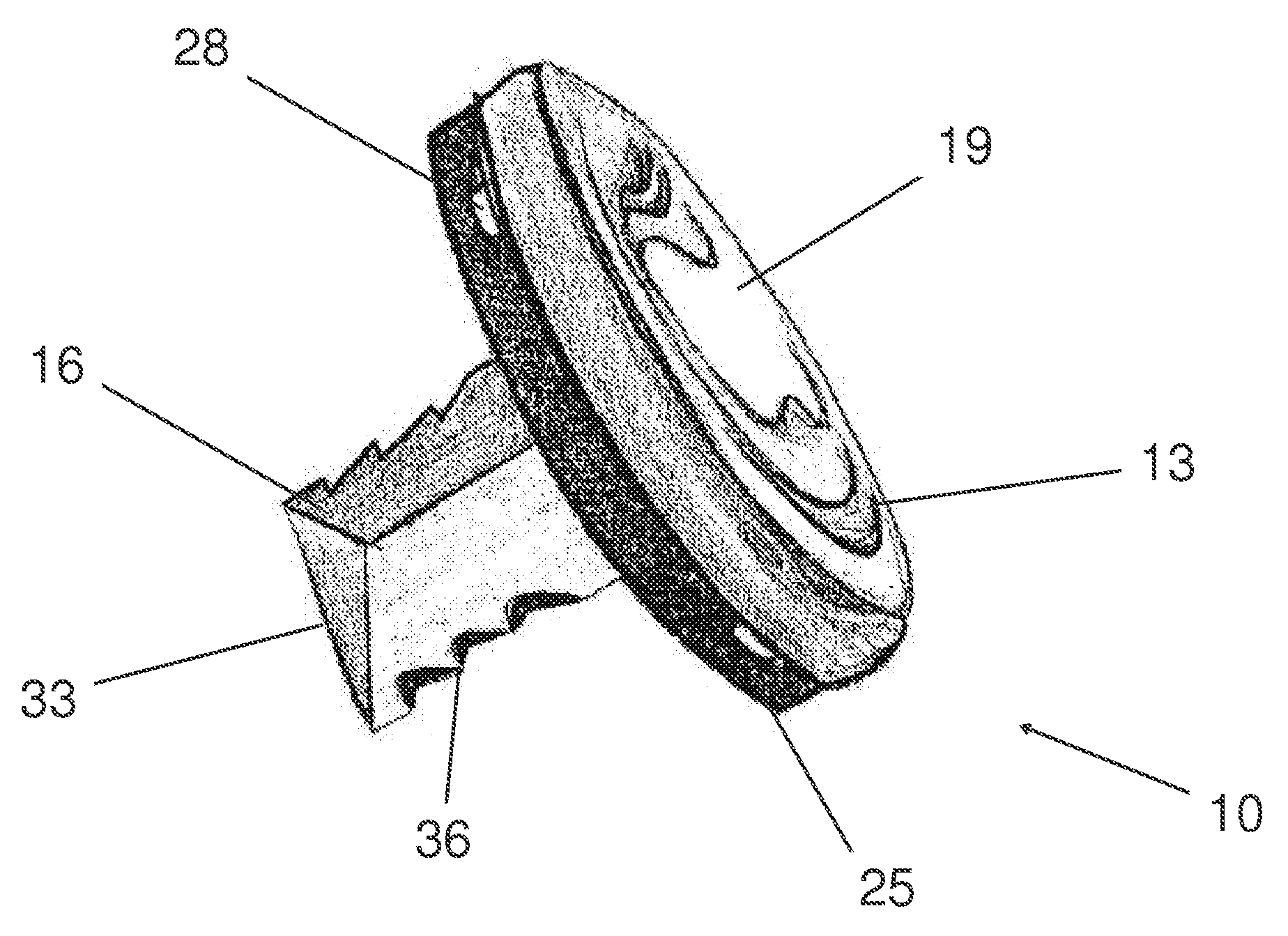
[0021]Referring to the drawings, FIG. 1 shows an implant, indicated generally as 10, according to certain aspects of a particularly preferred embodiment of the i...


PUM


Abstract

A joint resurfacing prosthetic implant system is disclosed having an anatomically-shaped implant to replace a joint at a pedal digit or finger, including a head having an elliptical bearing surface disposed for engaging the end of an adjacent bone and a seating surface opposite the bearing surface, an elongated stem extending distally from the seating surface, and a flange on the circumference of the device and extending distally from the seating surface. The flange includes one or more portals and a removed section configured to avoid impinging upon a tendon during and after implantation of the prosthetic. A specialized tool is also provided to facilitate the resection of the bone for implantation. The specialized tool includes an elliptical template having a cutting edge and a center insert that is sized and configured to match a reamer used to bore into the bone for insertion of the implant.

Description

CROSS REFERENCE TO RELATED APPLICATION[0001]This application is based upon and claims priority from co-pending U.S. Provisional Patent Application Ser. No. 61 / 486,385 entitled “Implantable Joint Resurfacing Prosthetic,” filed with the U.S. Patent and Trademark Office on May 16, 2011 by the inventor herein, the specification of which is incorporated herein by reference.FIELD OF THE INVENTION[0002]This invention relates in general to a prosthetic implant, and, more particularly, to a prosthetic implant system that resurfaces a bone, especially in the foot.BACKGROUND OF THE INVENTION[0003]The medical profession for many years has used prosthetic devices as joint surfaces to replace defective natural joints. Typically, such devices consist of one or two prosthetic members that are implanted into or attached to the anatomy of the subject at the location of the defective joint. In particular, various types of prosthetic joints have been developed to replace diseased or damaged human toe j...

Claims


Application Information

Patent Timeline
Patent Type & Authority Applications(United States)
IPC IPC(8): A61F2/30
CPCA61F2/4225A61F2/4241A61F2002/30151A61F2002/30253A61F2002/30299A61B17/1604A61F2002/30841A61F2002/30848A61F2002/30878A61F2002/30904A61F2002/30574A61F2002/30845
Inventor SLAVITT, JEROME A.
Owner SLAVITT JEROME A
Why Eureka
Try Eureka