Numerical controller with machining time prediction unit and machining error prediction unit

Active Publication Date: 2012-11-22
FANUC CORP
View PDF8 Cites 39 Cited by
  • Summary
  • Abstract
  • Description
  • Claims
  • Application Information

AI Technical Summary

Benefits of technology

[0026]The machining time prediction unit may determine a plurality of predicted machining times based on a plurality of designated precision data, and the machining error prediction unit may determine a plurality of predicted machining errors based on a plurality of designated speed data. The precision data and the speed data for the shortest predicted machining time within a preset machining error tolerance may be determined based on the plurality of predicted machining times and the plurality of predicted machining errors thus determined.
[0027]The numerical controller may control a multi-axis machine comprising a rotary axis, the machining error prediction unit may determine a three-dimensional command position point sequence and a three-dimensional servo position point sequence of a tool center point position based on the command position point sequence and the servo position point sequence, and the error between the command position point sequence and the servo position point sequence may be determined with the three-dimensional command position point sequence and the thre

Problems solved by technology

It is not easy, however, to ascertain the appropriate machining time and machining error level for the workpiece.
Although the machining time is predicted in the techniques disclosed in the above two patent documents, machining errors are not predicted.
Therefore, these techniques cannot meet users' demand to know by simulation the precision of the workpiece with the machining speed without trial machining or to know by simulation the machining speed at which the workpiece can be machined with a precision within a machining error tolerance in a minimum machining time without trial machining.
In modern numerical controllers, however, complicated speed control is performed for smooth acceleration/deceleration characteristics, such as linear and bell-shaped acceleration/deceleration characteristics, as well as the exponential acceleration/deceleration characteristics.
Thus, the machining error cannot

Method used


Image

  • Numerical controller with machining time prediction unit and machining error prediction unit
  • Numerical controller with machining time prediction unit and machining error prediction unit
  • Numerical controller with machining time prediction unit and machining error prediction unit

Examples


embodiment 1

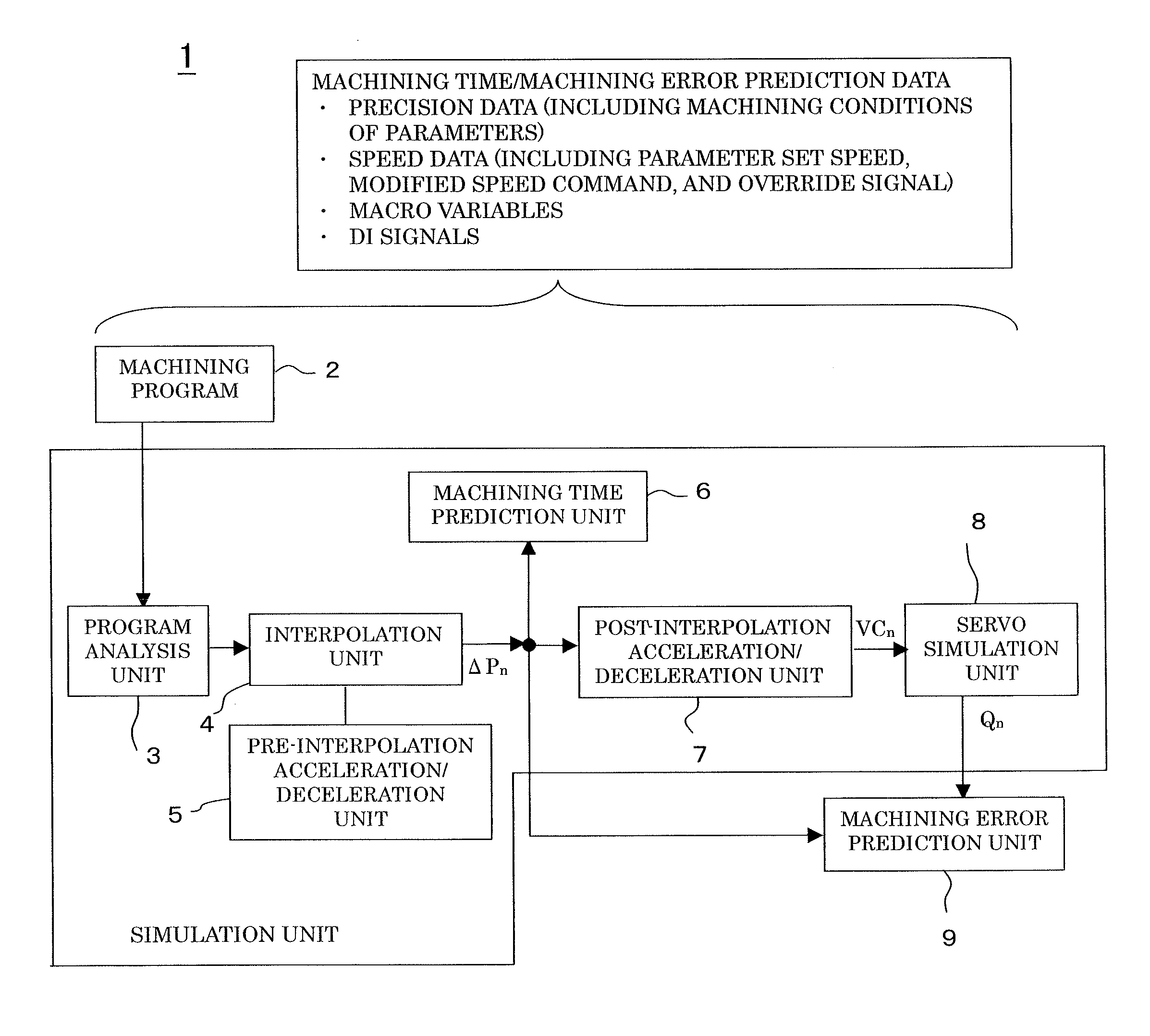
[0053]FIG. 5 is a functional block diagram of a numerical controller 1 according to the present invention, comprising a machining time prediction unit and a machining error prediction unit for a machining program.

[0054]A program analysis unit 3 simulates a program analysis process for reading and analyzing a machining program 2 and creating interpolation data. An interpolation unit 4 simulates an interpolation process such that interpolation is performed according to the interpolation data and interpolation data ΔPn are created, based on speed data created for blocks and corners between blocks by a pre-interpolation acceleration / deceleration unit 5. A post-interpolation acceleration / deceleration unit 7 simulates a post-interpolation acceleration / deceleration process such that post-interpolation acceleration / deceleration is performed for the interpolation data ΔPn and servo position command data VCn is created by accumulating the data. The servo position command data VCn is delivered...

embodiment 2

[0092]In Embodiment 2, conditions for the shortest machining time are determined within the machining error tolerance.

[0093]A table shown in FIG. 14 is created from predicted machining times Te and predicted machining errors Ee which are determined based on some of the converted precision data and speed data.

[0094]In this case, parameter set speeds are given as the speed data. FIG. 14 shows predicted machining times and predicted machining errors represented by those data in five boxed areas, i.e., (precision data: 1, speed data: 1,000 ram / min), (precision data: 10, speed data: 1,000 ram / min), (precision data: 5, speed data: 2,000 mm / min), (precision data: 1, speed data: 3,000 mm / min), and (precision data: 10, speed data: 3,000 mm / min). The predicted machining time Te (minutes) and predicted machining error Ee (mm) are entered in upper and lower columns, respectively, of each boxed area. Data in the other areas are obtained by interpolating the boxed data through proportional distri...

embodiment 3

[0096]In the case of a multi-axis machine having rotary axes (X-, Y-, Z-, B-, and C-axes) in a tool head and tables, a machining error prediction unit 9 can determine a three-dimensional command position point sequence Pn′ (PXn′, PYn′, PZn′) and a three-dimensional servo position point sequence Qm′ (QXm′, QYm′, QZm′) of a tool center point position, based on command position point sequences Pn (PXn, PYn, PZn, PBn, PCn) and servo position point sequences Qm (QXm, QYm, QZm, QBm, QCm) and a tool length, and predict a machining error by handling the determined command position point sequences and servo position point sequences in the same manner as the command position point sequences and servo position point sequences according to the first or second embodiments.

[0097]Although the subscripts B and C are used to represent positions of the assumed B- and C-axes of the multi-axis machine, the machine may have other rotary axes, A- and B-axes or A- and C-axes. Further, multi-axis machines ...


PUM


Abstract

In connection with a machining program used in machining a workpiece by means of a machine tool controlled by a numerical controller, interpolation data, a command position point sequence, and a servo position point sequence for each processing period are determined by simulation by designating speed data for giving a machining speed and precision data for giving a machining precision. A predicted machining time for workpiece machining is determined based on the determined interpolation data, and a predicted machining error for workpiece machining is determined based on the determined command and servo position point sequences. Further, the precision data and the speed data are determined for the shortest predicted machining time within a preset machining error tolerance, based on a plurality of predicted machining times and a plurality of predicted machining errors.

Description

BACKGROUND OF THE INVENTION[0001]1. Field of the Invention[0002]The present invention relates to a numerical controller with a machining time prediction unit and a machining error prediction unit.[0003]2. Description of the Related Art[0004]In machining a workpiece using a machine tool, in general, if the machining time is reduced or if the machining speed is increased, the machining precision is degraded. If the machining time is increased or if the machining speed is reduced, in contrast, the machining precision is improved. In the workpiece machining, the machining precision is more important than the machining time. Thus, users who use the machine tool to machine the workpiece wish to be able to machine the workpiece in a minimum machining time with a machining precision within a preset machining error tolerance. It is not easy, however, to ascertain the appropriate machining time and machining error level for the workpiece.[0005]Accordingly, machining is normally performed at a...

Claims


Application Information

Patent Timeline
IPC IPC(8): G05B19/416
CPCG05B19/4069G05B2219/36252G05B2219/36219G05B2219/35346Y02P90/02
Inventor OTSUKI, TOSHIAKIHANAOKA, OSAMU
Owner FANUC CORP
Why Eureka
Try Eureka