

Gas-liquid separator and multiphase flow rate measurement device
a gas-liquid separator and flow rate measurement technology, which is applied in the direction of liquid degasification, instruments, separation processes, etc., can solve the problems of large installation area, large volume increased cost of separation tank type gas-liquid separator, so as to achieve accurate measurement of flow rate
- Summary
- Abstract
- Description
- Claims
- Application Information
AI Technical Summary
Benefits of technology
Problems solved by technology
Method used
Image

Examples
first embodiment
1-1. Gas-Liquid Separator
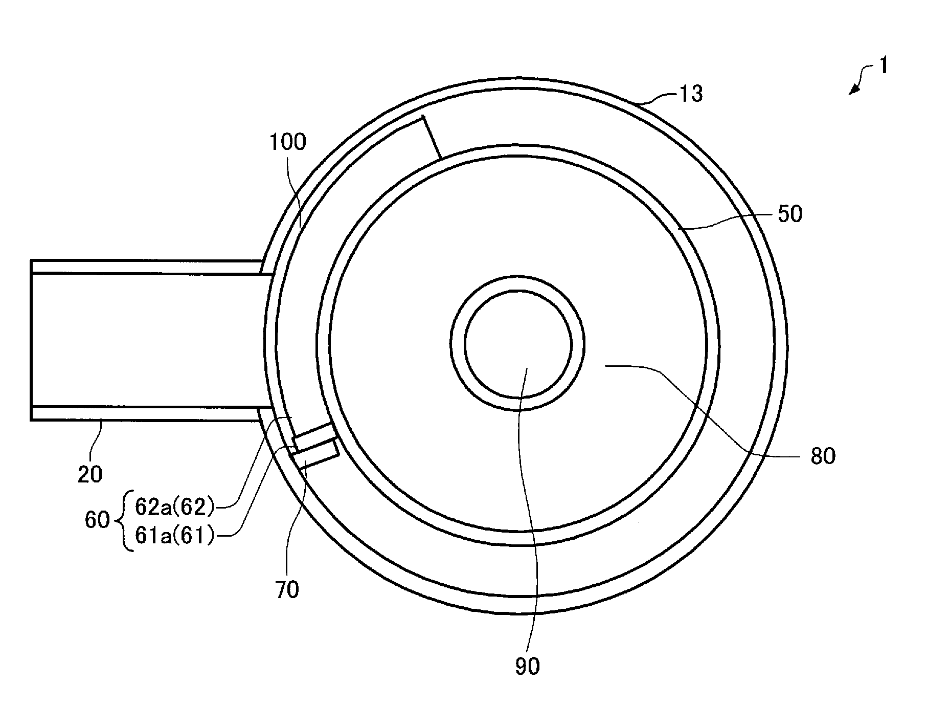
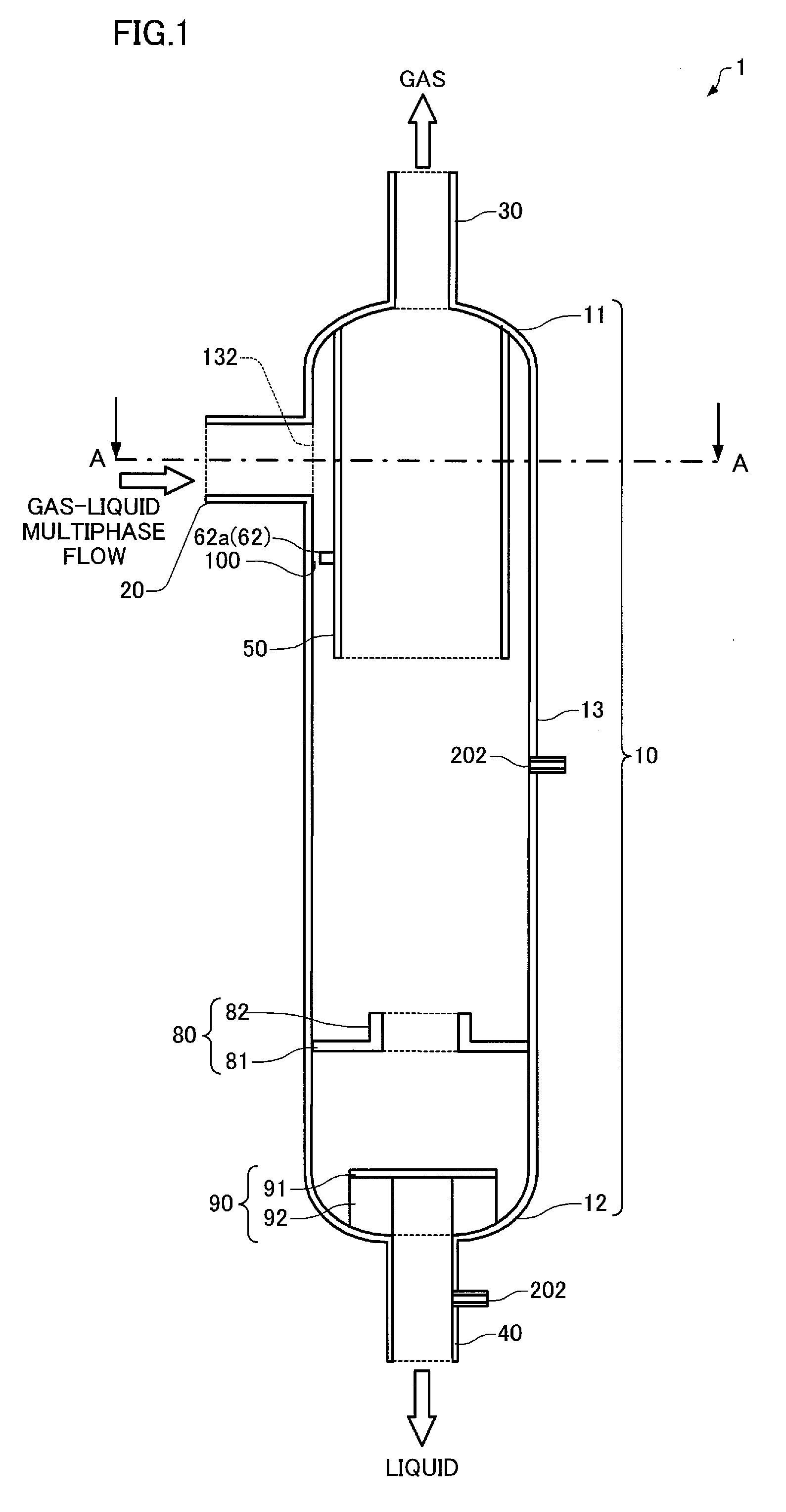
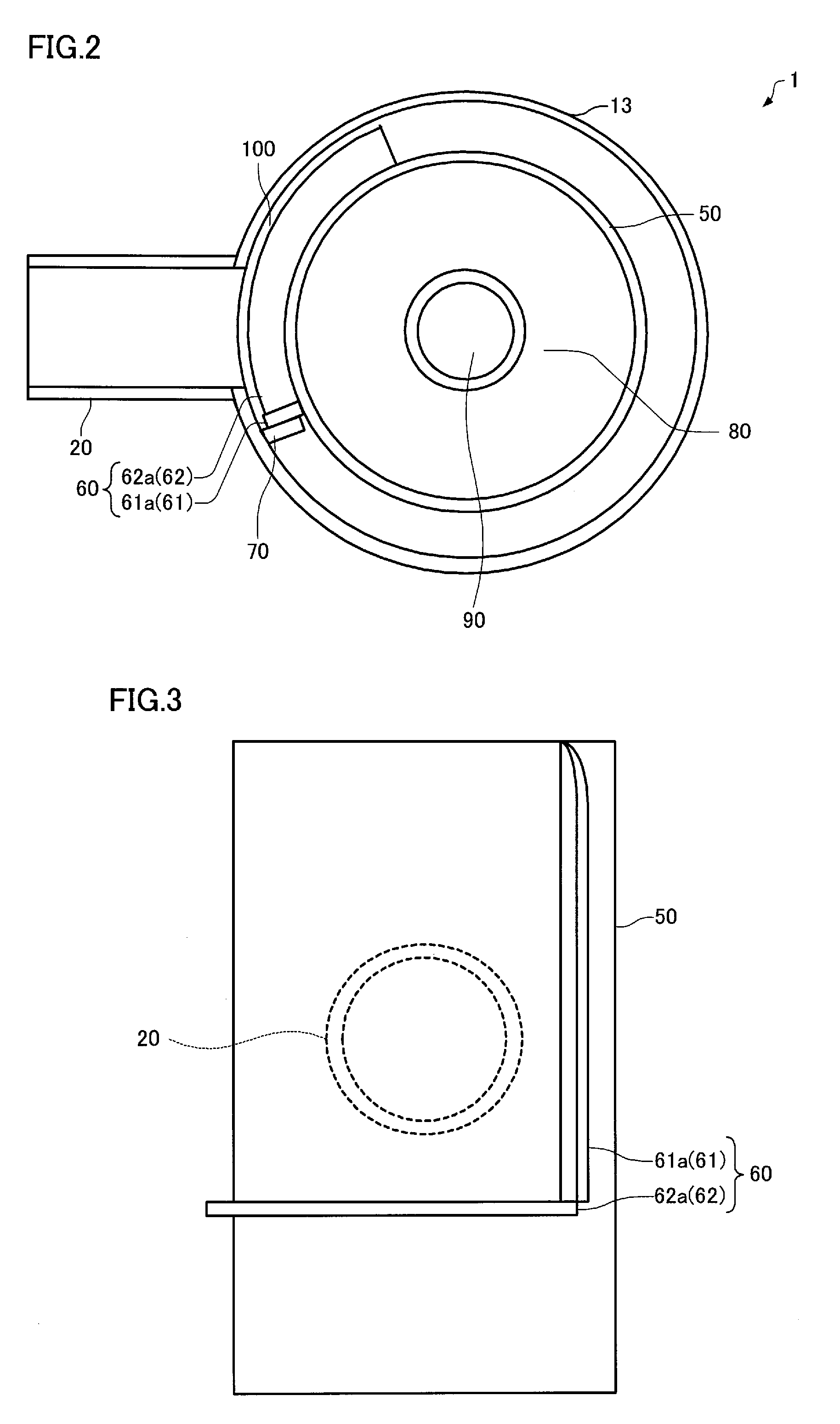
[0089]FIG. 1 is an exemplary schematic view illustrating the meridian cross section of a gas-liquid separator 1 according to a first embodiment. FIG. 2 is an exemplary schematic cross-sectional view illustrating the gas-liquid separator 1 according to the first embodiment taken along the line A-A in FIG. 1.
[0090]The gas-liquid separator 1 according to the first embodiment separates a gas-liquid multiphase fluid into gas and liquid, and includes a container 10 that includes a top section 11, a bottom section 12, and a hollow body section 13 that connects the top section 11 and the bottom section 12, an inlet pipe 20 that supplies a gas-liquid multiphase fluid to the container 10 via an inlet opening 132 formed in the side surface of the body section 13, a gas outlet pipe 30 that discharges gas via the top section 11, a liquid outlet pipe 40 that discharges liquid via the bottom section 12, a hollow inner pipe 50, the upper end of the inner pipe 50 being conne...
second embodiment
1-3. Gas-Liquid Separator
[0141]FIG. 14 is an exemplary schematic view illustrating the meridian cross section of a gas-liquid separator 2 according to a second embodiment. A configuration in which the gas-liquid separator 1 according to the first embodiment is combined with a droplet separator 110, a bubble separator 120, and a pipe 130 that connects the droplet separator 110 and the bubble separator 120 is described below as an example of the gas-liquid separator 2 according to the second embodiment. Note that the gas-liquid separator 2 according to the second embodiment may have a configuration in which the gas-liquid separator 1a, the gas-liquid separator 1b, the gas-liquid separator 1c, or the gas-liquid separator 1d is combined with the droplet separator 110, the bubble separator 120, and the pipe 130 that connects the droplet separator 110 and the bubble separator 120. Note that the same elements as those of the gas-liquid separator 1 according to the first embodiment are indi...
experimental examples
2. Experimental Examples
[0148]In the following experimental examples, gas-liquid separation was implemented using the gas-liquid separator 1 according to the first embodiment.
[0149]The gas-liquid separator 1 used for the experiments had a configuration in which the diameter of the inner side surface of the body section 13 was 200 mm, the diameter of the outer side surface of the inner pipe 50 was about 165 mm, the distance between the inner side surface of the body section 13 and the outer side surface of the inner pipe 50 was about 17 mm, and the diameter of the inner side surface of the inlet pipe 20 in the vertical direction was 50 mm. The guide plate lower section 62 was provided on the outer side surface of the inner pipe 50 within an angular range of 90° from the position directly under the guide plate side section 61 when viewed from above. The width of the space 100 formed between the guide plate lower section 62 and the inner side surface of the body section 13 was about 5 ...
PUM
| Property | Measurement | Unit |
|---|---|---|
| diameter | aaaaa | aaaaa |
| diameter | aaaaa | aaaaa |
| diameter | aaaaa | aaaaa |
Abstract
Description
Claims
Application Information