Resonant fly-back power converter and LED lighting unit powered therefrom

a power converter and fly-back technology, applied in the direction of efficient power electronics conversion, electric variable regulation, instruments, etc., can solve the problems of dynamic power loss associated with a switching behavior, the compactness of dc-dc converters may be limited, and the switching frequency that can be implemented, so as to achieve the effect of reducing power losses and avoiding voltage switching

Inactive Publication Date: 2012-11-29
NAHORLED
View PDF2 Cites 30 Cited by
  • Summary
  • Abstract
  • Description
  • Claims
  • Application Information

AI Technical Summary

Benefits of technology

[0008]According to an aspect of some embodiments of the present invention, there is provided a resonant fly-back converter with reduced power losses due to switching. According to some embodiments of the present invention, the fly-back converter is o...

Problems solved by technology

One of the drawbacks to high frequency switching is dynamic power losses associated with a switching behavior of the switches of the converter, e.g. MOSFETs.
Dynamic power loss...

Method used


Image

  • Resonant fly-back power converter and LED lighting unit powered therefrom
  • Resonant fly-back power converter and LED lighting unit powered therefrom
  • Resonant fly-back power converter and LED lighting unit powered therefrom

Examples


Embodiment Construction

[0074]The present invention relates to power converters and LED lighting units, and more particularly to power converters for LED lighting units.

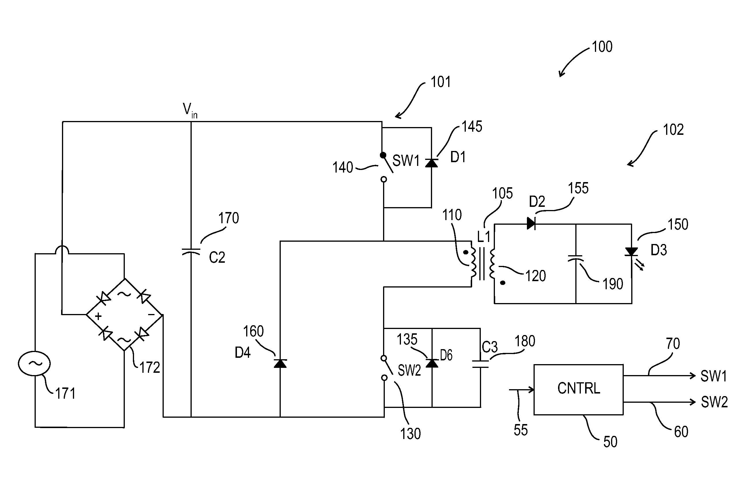
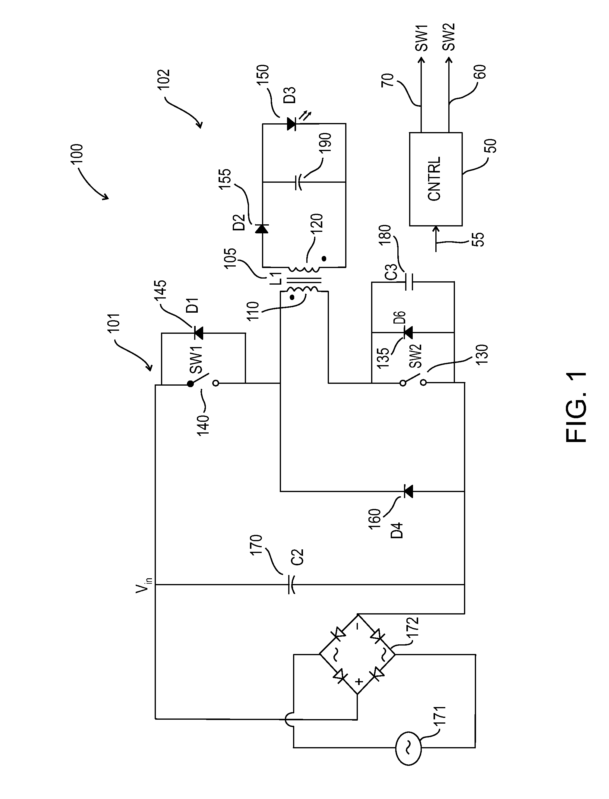
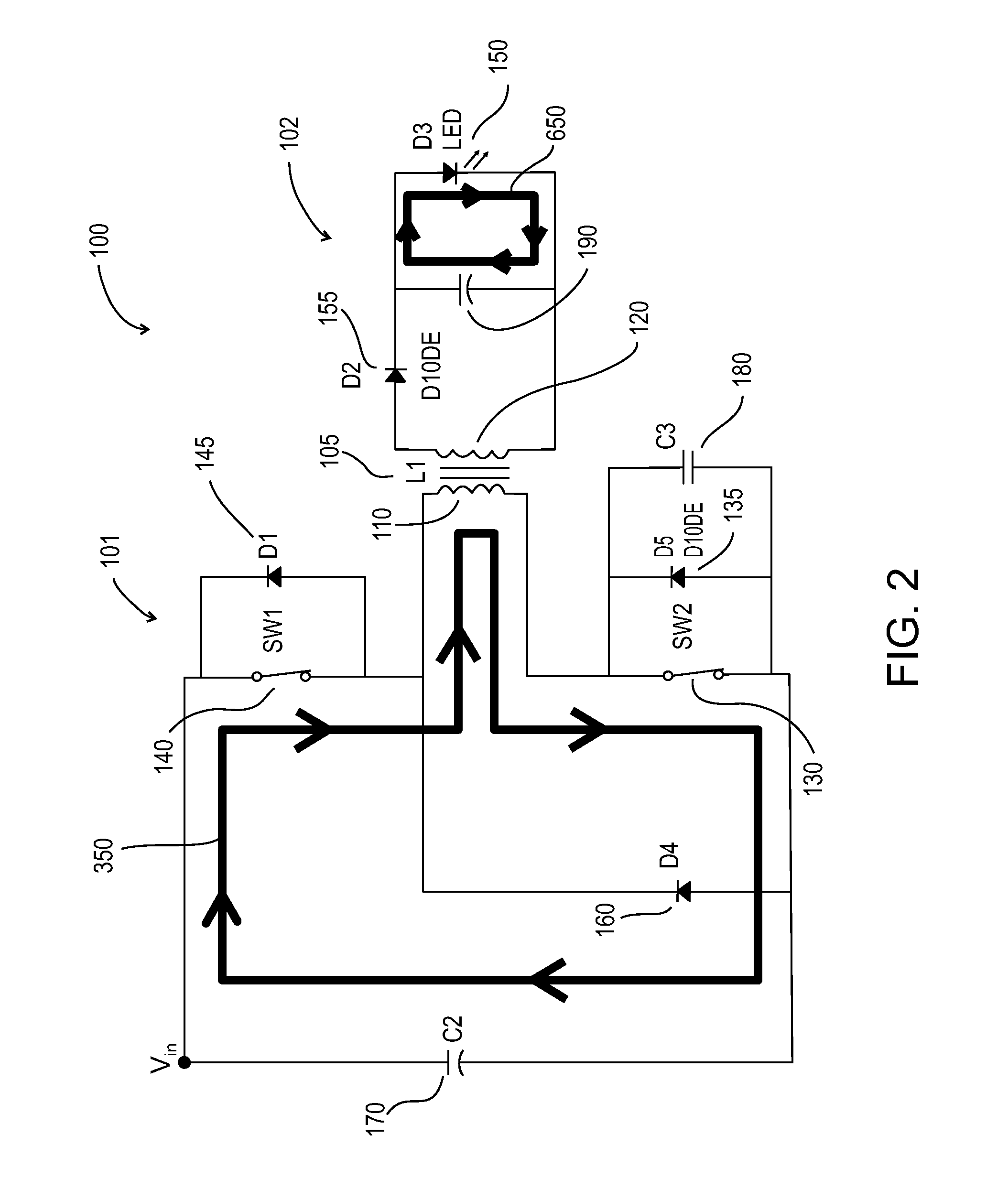
[0075]An aspect of some embodiments of the present invention is the provision of a resonant fly-back converter including a freeze-mode period operative to clamp the current on a primary winding for a pre-determined time prior to discharging current to the coupled secondary winding. According to some embodiments of the present invention, the pre-determined time corresponds to a desired delay required to synchronize switching with a first valley of a resonant oscillating voltage.

[0076]According to some embodiments of the present invention, the resonant fly-back converter operates with two PWM switching units and / or elements controlling a time period over which the primary winding is magnetized and a time period over which current on a primary winding is clamped for each pulse repetition cycle of the fly-back converter. The present inventor ...


PUM


Abstract

A method for controlling powering with a resonant fly-back power converter includes powering an output circuit including a load, with a inductor of a resonant fly-back power converter including a primary winding electrically connected to an input circuit of the fly-back converter and secondary winding electrically connected to the output circuit of the fly-back converter, operating the converter in a discontinuous conduction mode. Charging and discharging of the primary winding is controlled with a first and second switching element and a capacitor connected across the second switching element selected for resonating with the primary winding. Both first and second switching elements are operative to connect primary winding to an input voltage source over a defined on-time. The pulsing of the first and second switching elements is synchronized and the on-time of the second switching element is extended with respect to the on-time of the first switching element.

Description

FIELD OF THE INVENTION[0001]The present invention relates to power converter and LED lighting units, and more particularly to power converters for LED lighting units.BACKGROUND OF THE INVENTION[0002]Switching Mode Power Supplies (SMPS) are electronic power supplies that include electronic switches which commutate on and off at high frequency to connect and disconnect an energy storage inductor(s) and capacitor(s) to and from an input source or an output. By varying duty cycle, frequency or phase shift of the commutations, an output parameter, such as output voltage or current is controlled. SMPS are typically used to transfer power from an electrical power grid to an electronic device such as a personal computer. SMPS are also known to be used for powering LED lighting modules. SMPS may be used as AC-DC rectifiers, DC-DC voltage converters, DC-AC inverters, and / or AC-AC frequency changers.[0003]LED lighting modules are becoming more common in many applications for replacing less eff...

Claims


Application Information

Patent Timeline
IPC IPC(8): H02M3/335H05B37/02H05B44/00
CPCH02M3/3353H02M7/003Y02B70/1433Y02B20/346H05B33/0815Y02B20/30Y02B70/10H05B45/385H02M3/003
Inventor AHARON, ILAN
Owner NAHORLED
Why Eureka
Try Eureka