Chest diagnostic support information generation system

a technology of information generation system and chest, which is applied in the field of chest diagnostic support information generation system, can solve the problems of requiring a large amount of processing time and unable to obtain the relating to blood flow as accurate as the featur

Active Publication Date: 2012-11-29
KONICA MINOLTA INC
View PDF2 Cites 52 Cited by
  • Summary
  • Abstract
  • Description
  • Claims
  • Application Information

AI Technical Summary

Benefits of technology

[0009]One aspect of the present invention is to supply accurate diagnostic support information relating to each of the breathing and the blood flow by one time of motion imaging.

Problems solved by technology

In International Application Publication 2009 / 090894, although both the feature amounts relating to the breathing and the blood flow can be calculated by the imaging data of one time, quite an amount of processing time is required in order to get an accurate analysis result because a warping processing at each accurate small region becomes indispensable, and there is a defect that it is difficult to obtain the relating to blood flow as accurate as the feature amount relating to the breathing because both the feature amount are calculated by the same processing algorism (difference signal value between frames).

Method used


Image

  • Chest diagnostic support information generation system
  • Chest diagnostic support information generation system
  • Chest diagnostic support information generation system

Examples


1st embodiment

[Configuration of the Chest Diagnostic Support Information Generation System 100]

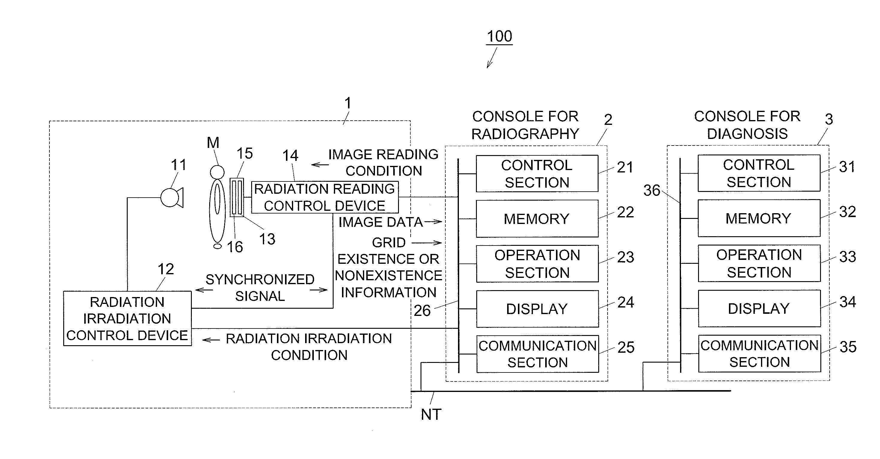
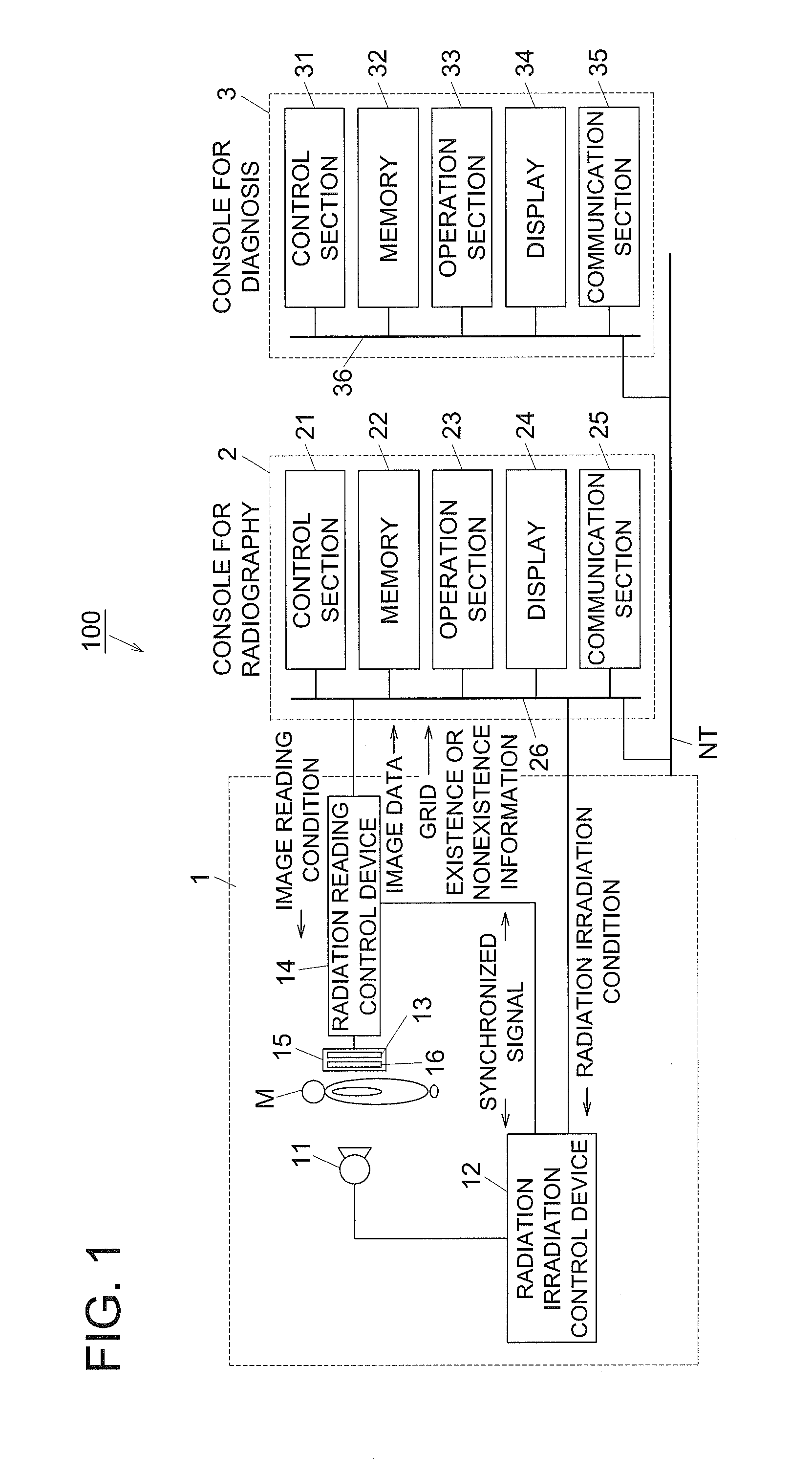
[0040]The configuration of the 1st embodiment is explained first. The whole configuration of the chest diagnostic support information generation system 100 of the 1st embodiment is shown in FIG. 1.

[0041]As shown in FIG. 1, the chest diagnostic support information generation system 100 is configured by that a radiography equipment 1 and a console for radiography 2 are connected via a telecommunication cable and so on, and the console for radiography 2 and a console for diagnosis 3 are connected via a communication network NT, such as LAN (Local Area Network). Each equipment which constitutes the chest diagnostic support information generation system 100 is in accordance with DICOM (Digital Image and Communications in Medicine) standard, and communication between each equipment is performed in conformity with DICOM.

[Configuration of Radiography Equipment 1]

[0042]Radiography equipment 1 is an equipment whi...

2nd embodiment

[0185]Next, the configuration of the 2nd embodiment of the invention is explained.

[0186]In the 2nd embodiment, the case of the application of this invention to the portable chest diagnostic support information generation system 70 for patients who are difficult to move is explained.

[0187]As shown in FIG. 24, the portable chest diagnostic support information generation system 70 is a system which is carried into the patient room Rc and so on together with the round visiting car 71 and takes radiograph by irradiating radiation from the portable radiation source 52P in the state where the FPD cassette 72 is inserted between the body of the radiographic subject H which is lying down on Bed B, for example, to generate diagnostic support information.

[0188]As shown in FIG. 24, the portable chest diagnostic support information generation system 70 is provided with the portable radiation source 52P and the radiation generating equipment 57 carried on the visiting car 71. And the console C an...


PUM

PropertyMeasurementUnit
timeaaaaaaaaaa
timeaaaaaaaaaa
cutoff frequencyaaaaaaaaaa

Abstract

A chest diagnostic support information generation system includes: a radiography section which radiographs a chest portion of a subject; an image analysis section which generates a diagnostic support information based on an image data generated by the radiography section; and a display which displays the diagnostic support information, wherein the radiography section obtains a plurality of frame images which show a motion state of the chest of the subject, and the image analysis section includes: a breathing information generation section which generates the diagnostic support information relating to breathing of the subject based on a difference value of the pixel or the block corresponded with each other between image frames temporally adjacent among the plurality of frame images; and a blood flow information generation section which generates the diagnostic support information relating to blood flow of the subject based on a generated output signal wave form.

Description

[0001]This application is based on Japanese Patent Application No. 2011-115601 filed on May 24, 2011, in Japan Patent Office, the entire content of which is hereby incorporated by reference.TECHNICAL FIELD[0002]The present invention relates to a chest diagnostic support information generation system.BACKGROUND[0003]Motion images of the diagnostic subject portion taken by using a semiconductor image sensor such as FPD (Flat Panel Detector) are increasingly tried to be applied to diagnosis, compared with conventional still imaging and diagnosis using films or photostimulable phosphor plates. Specifically, by utilizing the quick response in reading and erasing image data of semiconductor image sensors, continuous irradiation or consecutive pulsed irradiation is carried out from a radiation source corresponding to a timing of reading and erasing of the semiconductor image sensor to take plural images per second and thereby the motion image of the diagnostic portion is taken. A doctor ca...

Claims


Application Information

Patent Timeline
Patent Type & Authority Applications(United States)
IPC IPC(8): G01N23/04
CPCA61B6/4291G06T2207/30061A61B6/463A61B6/468A61B6/486A61B6/507A61B6/5205A61B6/5217A61B6/5235A61B6/5258A61B6/542G06T7/0016G06T2207/10016G06T2207/10116A61B6/4405G16H50/30
Inventor SHIMADA, TETSUOMURAOKA, SHINTARONOJI, SHO
Owner KONICA MINOLTA INC
Why Eureka
Try Eureka