Kinematic Predictor for Articulated Mechanisms

a kinematic predictor and articulated mechanism technology, applied in the field of articulated mechanism, can solve problems such as quick intractableness, and achieve the effect of simplifying the definition

Active Publication Date: 2012-11-29
WISCONSIN ALUMNI RES FOUND
View PDF6 Cites 8 Cited by
  • Summary
  • Abstract
  • Description
  • Claims
  • Application Information

AI Technical Summary

Benefits of technology

[0021]It is thus an object of the invention to provide a formalism that greatly simplifies the definition of the differential equations, the inputting of a desired joint trajectory and the intervening calculations.

Problems solved by technology

An important robot control problem involves determining the angles or extensions of the various joints necessary to position the robot tool (effector) in a desired orientation and location.
Determining higher derivatives of a complicated loop equation may be done symbolically with significant manual effort or with a symbolic algebra software package, but quickly becomes intractable owing to the rapid growth in the number of terms that precludes checking such symbolic expressions for correctness or their practical implementation in computer software.

Method used


Image

  • Kinematic Predictor for Articulated Mechanisms
  • Kinematic Predictor for Articulated Mechanisms
  • Kinematic Predictor for Articulated Mechanisms

Examples


example i

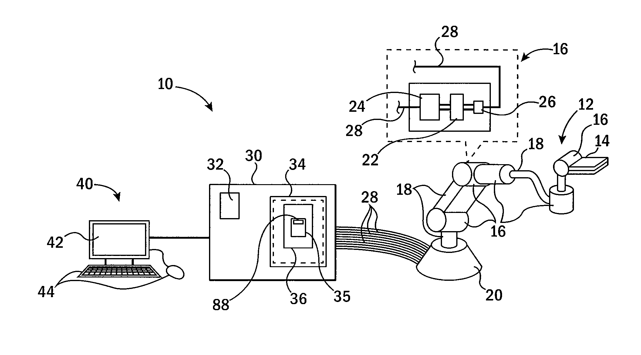
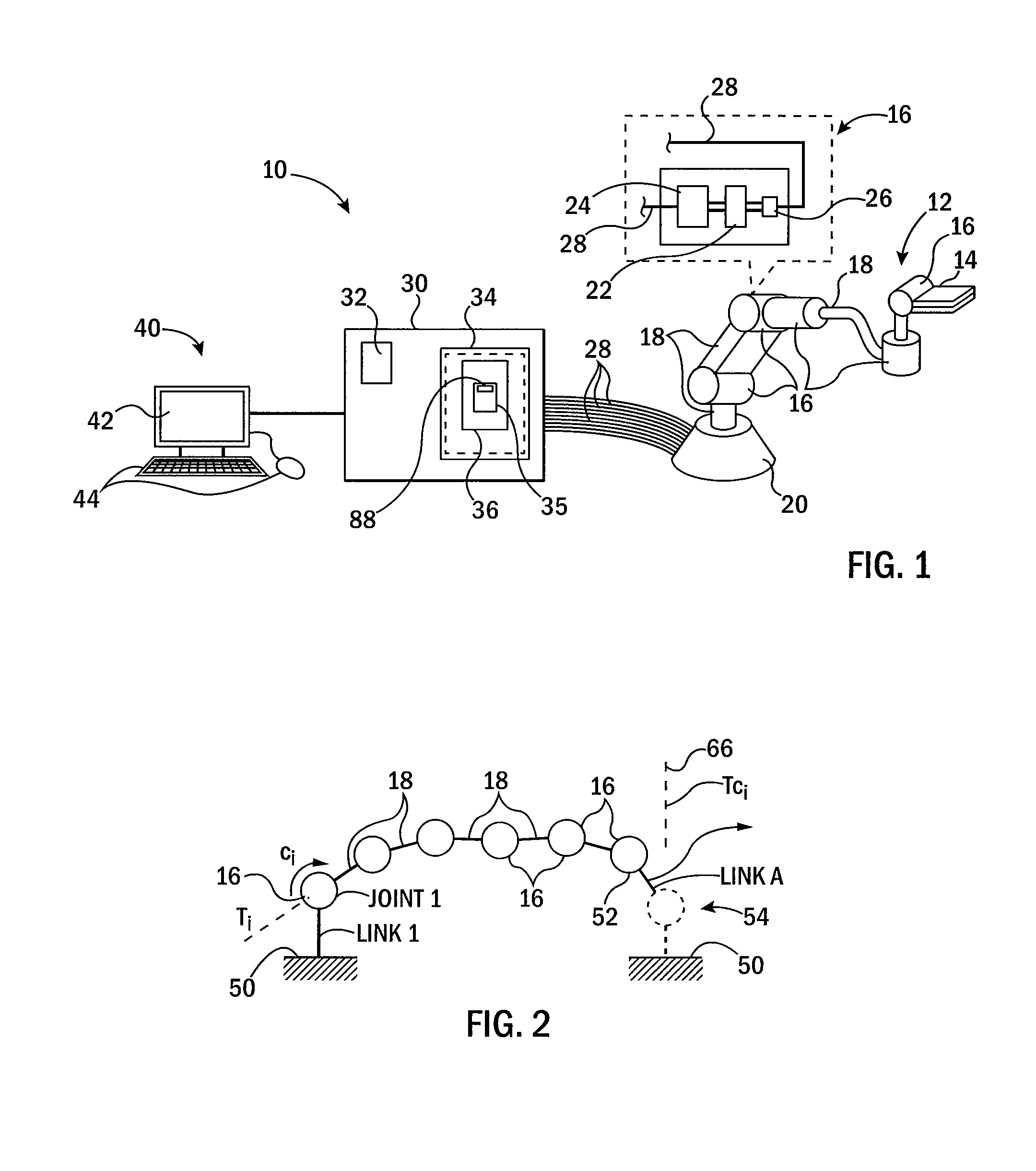
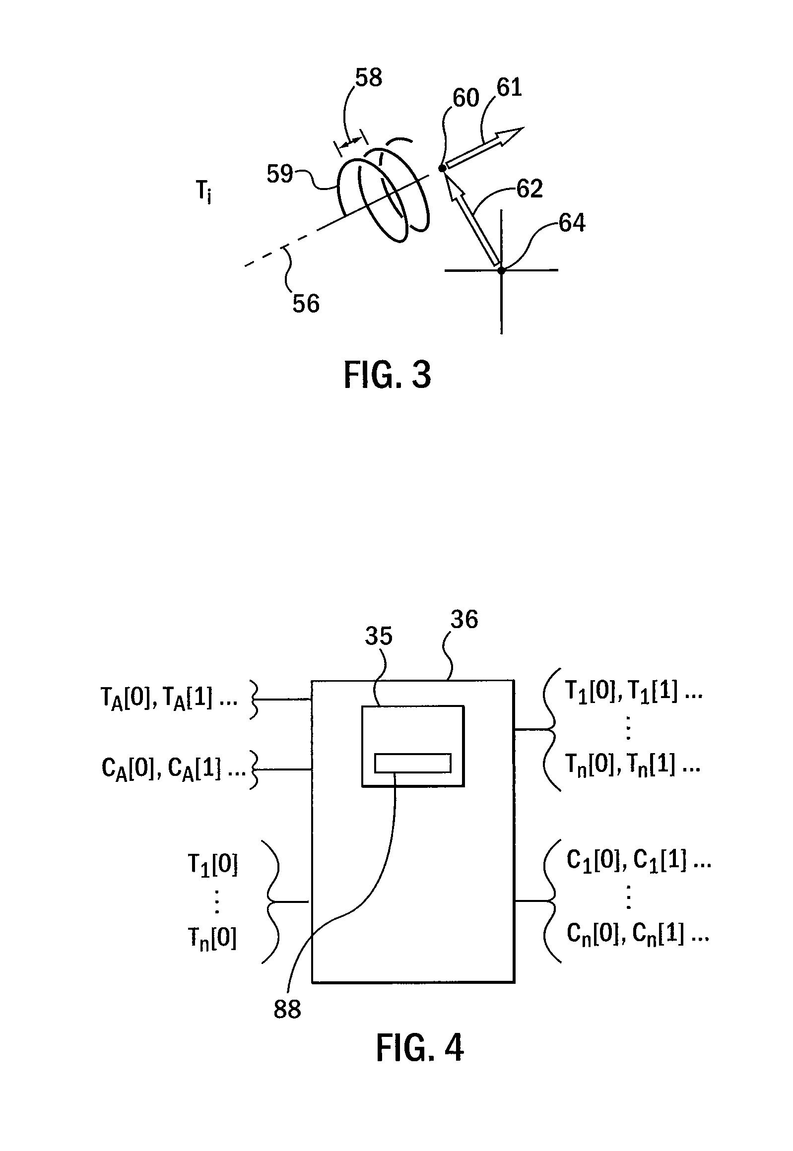
[0060]Referring now to FIG. 7, an example articulated linkage 12 is shown providing 8 joints 16 (only joints 1-4 labeled for clarity) and associated links 18. A final effector 14 rests on top of a workpiece 100 and may, for example, be commanded to move in a circular trajectory on an upper face of the workpiece 100 to provide a polishing motion. This command may be expressed as a simple motion of a virtual ninth joint. The screw axes having initial positions Ti=Ti(0) and changing dynamically as Ti(t) over time t are depicted.

[0061]This same mechanism is abstracted in FIG. 8 to fully label each axis and to show the ninth virtual joint 54 that may, for example, define a simple circular polishing motion of the effector 14 attached to the virtual joint 54. Virtual joint 54 further closes the articulated linkage 12.

[0062]The following process solves a closed kinematic loop for power series coefficients of the “passive” subset of joint rates Ci (index i restricted to those passive joints,...


PUM


Abstract

A predictor usable for rapid and accurate calculation of joint commands of an articulated mechanism describes relationship between the joints in the form of a differential equation. The predictor solves this differential equation by direct substitution of a power series for each of its variables and the combining of selected sets of coefficients of these power series into linear systems of equations which may be solved to determine power series coefficients to arbitrary order.

Description

CROSS REFERENCE TO RELATED APPLICATION[0001]This application claims the benefit of U.S. provisional application 61 / 526,309 filed Aug. 23, 2011 and the benefit of U.S. provisional application 61 / 521,449 filed Aug. 9, 2011 both hereby incorporated by reference.STATEMENT REGARDING FEDERALLY SPONSORED RESEARCH OR DEVELOPMENTBackground of the Invention [0002]The present invention relates to articulated mechanisms, such as but not limited to robot arms, and more particularly to a predictor for determining joint positions and rates for multiple joints based on a desired movement of one or more other joints, such as is necessary for control or design of articulated mechanisms.[0003]Articulated mechanisms such as a robot arm can be understood as a set of rigid links connected to each other by joints. The joints for a robot arm may be associated with actuators such as motors to move the joints and sensors providing an indication of joint position. Common joints include so-called revolute join...

Claims


Application Information

Patent Timeline
Patent Type & Authority Applications(United States)
IPC IPC(8): G01B21/00G06F15/00
CPCA61B18/18A61B2018/00023A61B18/1815
Inventor MILENKOVIC, PAUL H.
Owner WISCONSIN ALUMNI RES FOUND
Why Eureka
Try Eureka