Electromagnetically actuatable valve

a technology of actuation valve and actuation valve, which is applied in the direction of valve operating means/release devices, machines/engines, etc., can solve the problems of reducing the switching time or the dynamic of the fuel injector, and achieve the effect of short production time, reduced eddy current losses, and consistent strength of the magnetic circui

Active Publication Date: 2012-12-06
ROBERT BOSCH GMBH
View PDF13 Cites 8 Cited by
  • Summary
  • Abstract
  • Description
  • Claims
  • Application Information

AI Technical Summary

Benefits of technology

[0007]The valve preferably includes at least one component of the magnetic actuator having exactly four sectors and four separating webs. As a result, even a small number of sectors and separating webs causes the eddy current losses to be reduced drastically in the case of magnetic field changes.
[0008]According to another preferred embodiment, the separating webs have a width which is selected in such a way that neighboring sectors are reliably separated in a straight manner from one another electrically. By minimizing the width and the material portion of the separating webs, only a slight amount of soft magnetic material of the magnet armature is lost, thus ensuring that the strength of the magnetic circuit is essentially consistent.
[0009]Preferably at least one component of a magnetic actuator is manufactured using a PIM method (powder injection molding method). Using this multi-component powder injection molding process instead of a turning process makes it possible to manufacture components of a magnetic actuator with short production times and low unit costs in a simple way. The method according to the present invention may be designed in such a way that the insulating separating webs are manufactured in a first step, the insulating separating webs are then held mechanically in a die, and the sectors made of soft magnetic material are subsequently injection-molded. Alternatively, the soft magnetic sectors may be manufactured in a first step. Subsequently, these sectors are placed into a die and held in position with the aid of a magnetic field, and the separating webs are injection-molded into the intermediate spaces between the soft magnetic sectors in a subsequent step. Thus, a cost-effective manufacture of a component for a magnet armature may be implemented according to the present invention, the component having thin-walled, electrically non-conductive separating webs between soft magnetic sectors. This makes it possible to minimize the formation of eddy currents which counteract the build-up and reduction of fields. The separating webs must be as thin-walled as poss

Problems solved by technology

The electrical properties of the material and the 360°-closed contour of the components cause eddy current losses and consequen

Method used


Image

  • Electromagnetically actuatable valve
  • Electromagnetically actuatable valve

Examples


Embodiment Construction

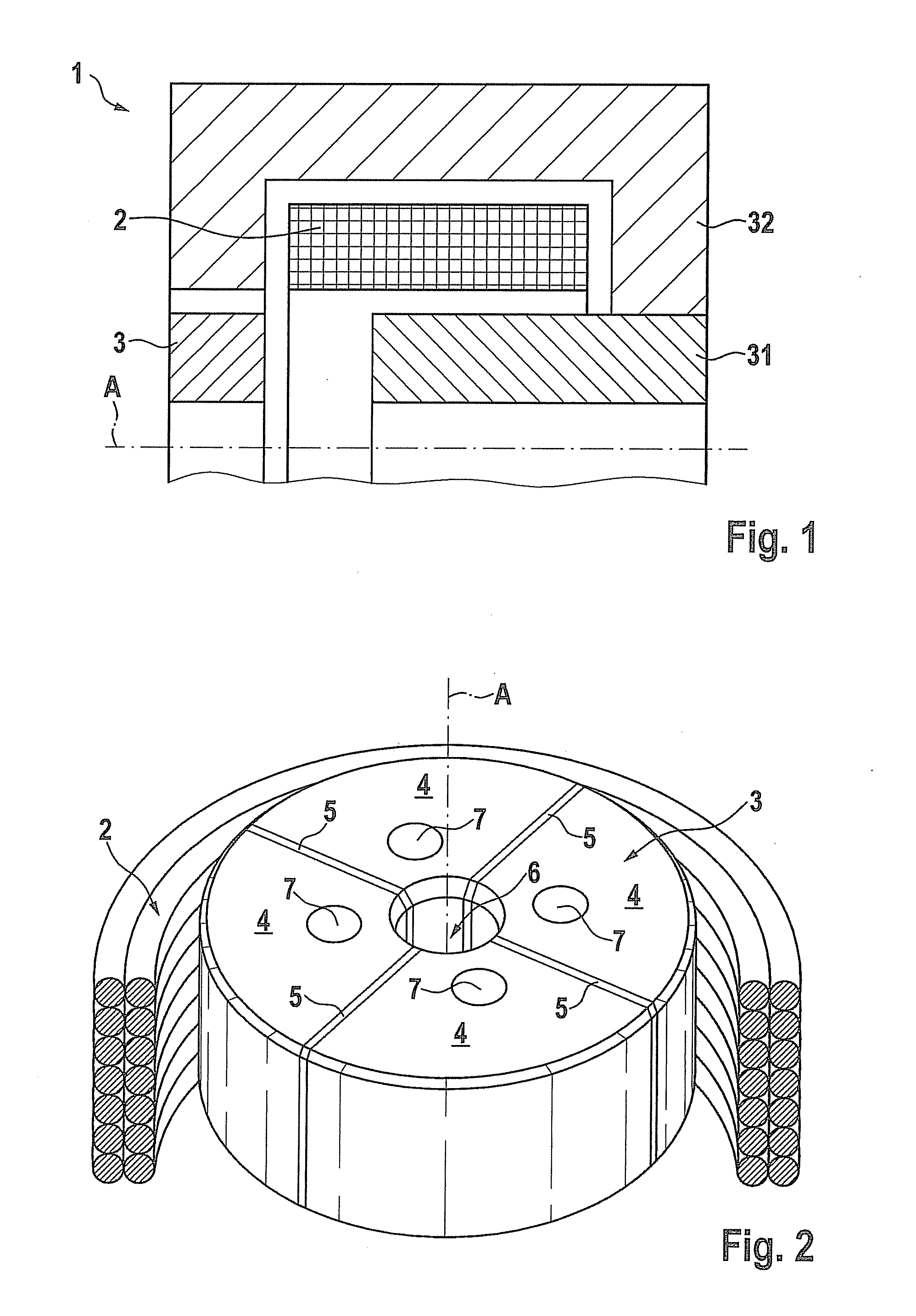
[0013]With reference to FIGS. 1 and 2, a fuel injector for injecting fuel according to a preferred exemplary embodiment of the present invention and a method for manufacturing a magnet armature of a magnetic actuator of fuel injector 1 are described in detail below.

[0014]As is apparent from the perspective representation of FIG. 1, the valve includes a magnetic actuator 1 having a magnet armature 3, a pole core 31, a valve jacket 32 as a feedback element and a coil 2 which surrounds magnet armature 3. Magnet armature 3 manufactured from a soft magnetic material has a central through opening 6 situated in an axial direction A, a valve needle (not shown in the representation) being situated in the through opening. Furthermore, magnet armature 3 has four fuel openings 7 running in axial direction A, each of which being situated in one of four sectors 4. As is further apparent from FIG. 2, each sector 4 includes essentially one fourth of the volume of magnet armature 3 in the circumfere...


PUM

PropertyMeasurementUnit
Widthaaaaaaaaaa

Abstract

An electrically actuatable valve for injecting fuel includes a magnetic actuator having multiple components, at least one component of the magnetic actuator having multiple sectors made of soft magnetic material and multiple insulating separating webs. A separating web is situated between each two neighboring sectors and entirely separates the neighboring sectors from one another electrically.

Description

BACKGROUND OF THE INVENTION[0001]1. Field of the Invention[0002]The present invention relates to an electromagnetically actuatable valve, in particular a fuel injector, having a magnetic actuator, as well as a method for manufacturing components of a magnetic actuator, for example, a magnet armature.[0003]2. Description of the Related Art[0004]High-pressure injectors of the related art are essentially designed as conventional solenoid switching valves having a coil and components of a magnetic actuator, for example, a magnet armature, an internal pole, an external pole, which are manufactured as turned parts from a soft magnetic bar material. The electrical properties of the material and the 360°-closed contour of the components cause eddy current losses and consequently a reduced switching time or dynamics of the fuel injector when the magnetic field is built up and reduced during operation.BRIEF SUMMARY OF THE INVENTION[0005]The electromagnetically actuatable valve according to th...

Claims


Application Information

Patent Timeline
IPC IPC(8): F16K31/02
CPCB22F3/225F02M51/0664F02M63/007F02M2200/08Y10T29/4902H01F7/081H01F41/0246H01F2007/086H01F2007/1676F02M2200/8046F16K31/0655
Inventor POHLMANN, JENSGRANER, JUERGEN
Owner ROBERT BOSCH GMBH
Why Eureka
Try Eureka