
Resonant-recovery power-reduction technique for boost converters

a power-recovery and boost converter technology, applied in the direction of electric variable regulation, process and machine control, instruments, etc., can solve the problems of power dissipation, switching losses can dissipate a significant amount of power, and the source of power dissipation arises, so as to reduce the output voltage ripple

Inactive Publication Date: 2012-12-06
APPLE INC
View PDF8 Cites 9 Cited by
  • Summary
  • Abstract
  • Description
  • Claims
  • Application Information

AI Technical Summary

Benefits of technology

[0014]In some embodiments, the system additionally includes a capacitive filter coupled to the output to reduce output voltage ripple.

Problems solved by technology

One source of power dissipation is the “boost converters,” which are commonly used to convert a battery voltage to higher voltage.
Another source of power dissipation arises from the “switching losses,” which result from charging and discharging the internal capacitances within the boost converter.
These switching losses can dissipate a significant amount of power, particularly so after the AC and DC conduction losses have been carefully balanced.

Method used


Image

  • Resonant-recovery power-reduction technique for boost converters
  • Resonant-recovery power-reduction technique for boost converters
  • Resonant-recovery power-reduction technique for boost converters

Examples


Embodiment Construction

[0023]The following description is presented to enable any person skilled in the art to make and use the disclosed embodiments, and is provided in the context of a particular application and its requirements. Various modifications to the disclosed embodiments will be readily apparent to those skilled in the art, and the general principles defined herein may be applied to other embodiments and applications without departing from the spirit and scope of the disclosed embodiments. Thus, the disclosed embodiments are not limited to the embodiments shown, but are to be accorded the widest scope consistent with the principles and features disclosed herein.

[0024]The data structures and code described in this detailed description are typically stored on a non-transitory computer-readable storage medium, which may be any device or medium that can store code and / or data for use by a computer system. The non-transitory computer-readable storage medium includes, but is not limited to, volatile ...


PUM


Abstract

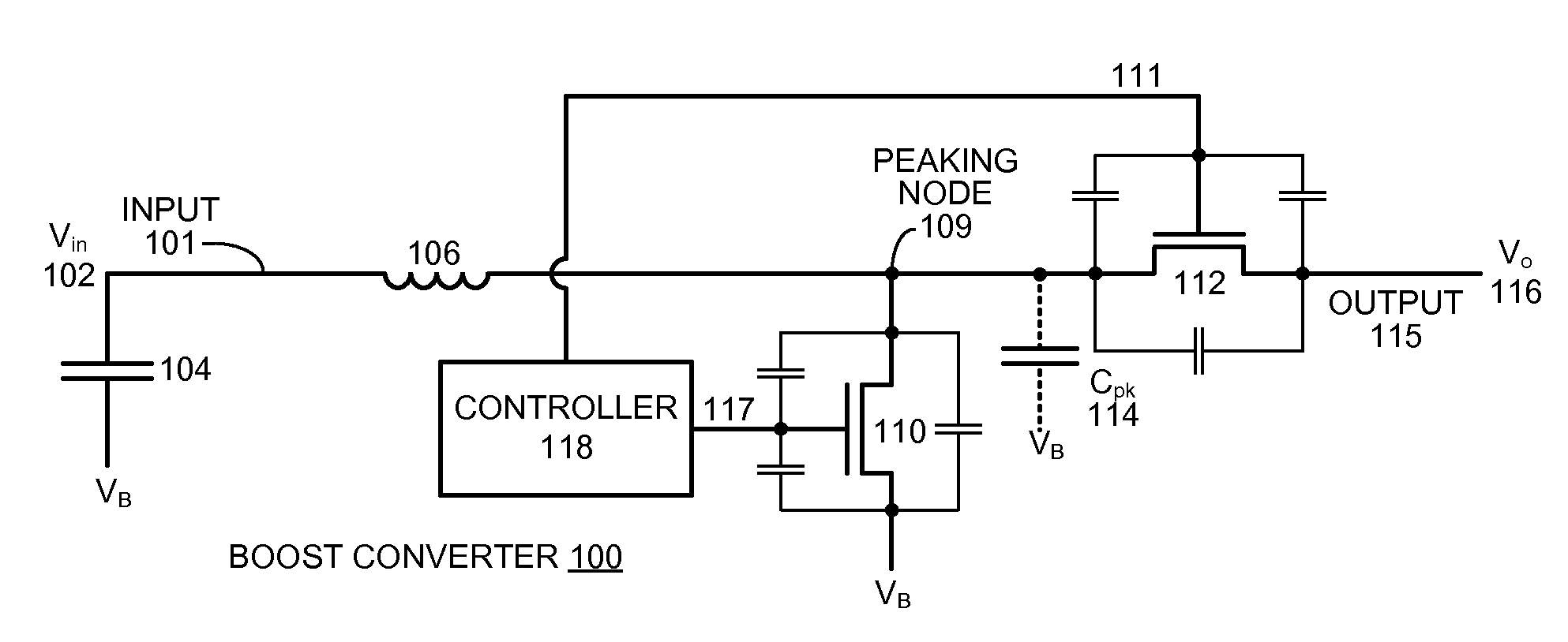
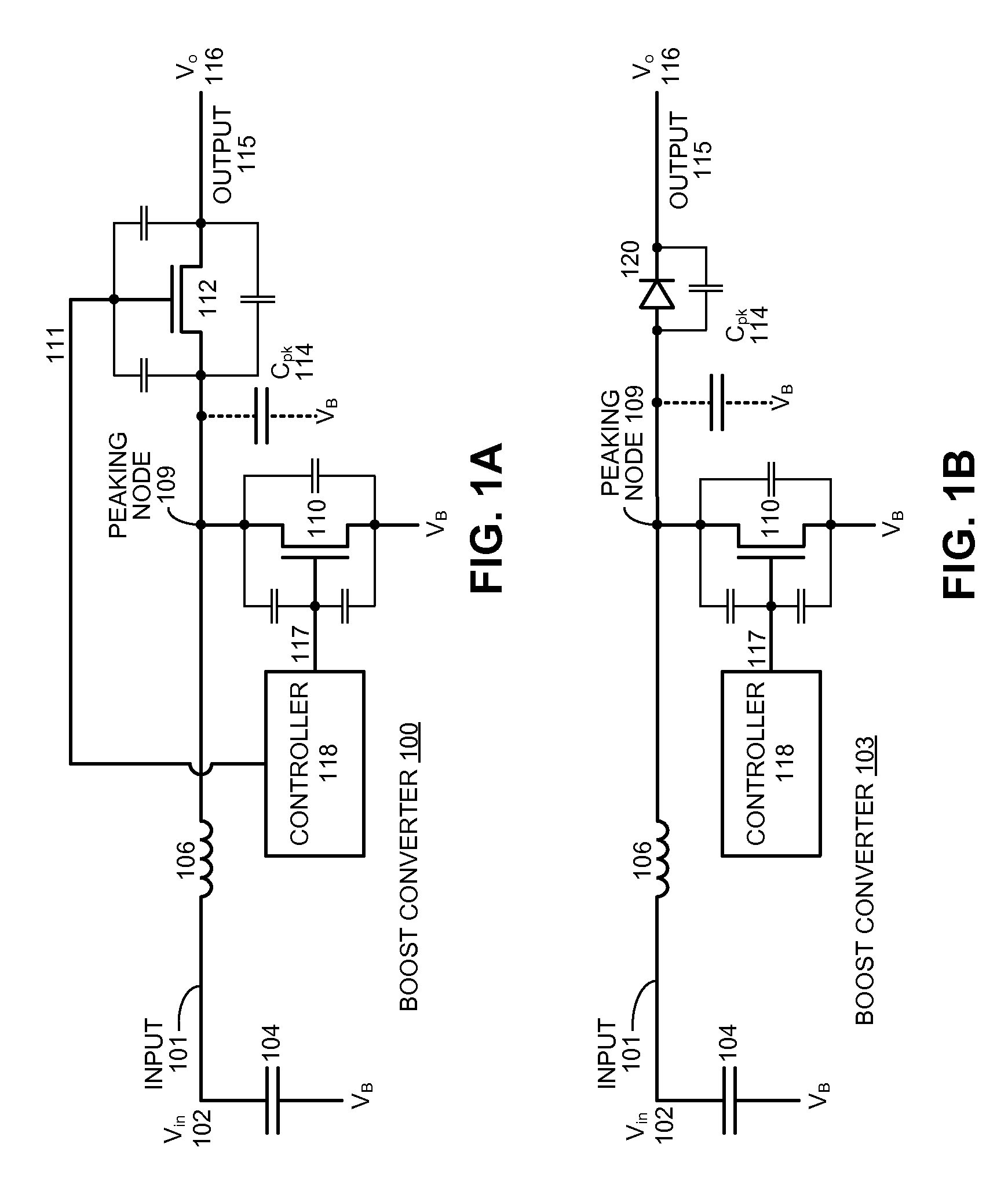
The disclosed embodiments relate to a power converter system. This power converter system includes an inductor which is coupled between an input that receives an input voltage Vin and a peaking node. The system also includes a low-side switch and a high-side switch, wherein the low-side switch is coupled between the peaking node and a base voltage, and the high-side switch is coupled between the peaking node and an output that produces an output voltage Vo. The system additionally includes a controller which cycles the low-side switch between on and off states with a cycle time Tcycle. During the on state, the inductor current can flow through the low-side switch to the base voltage, and during the off state, the inductor current can flow through the high-side switch to the output. Moreover, during the off state, the controller waits to turn on the low-side switch until the inductor current IL decreases from a peak current Ipk to zero and then goes negative. This negative inductor current resonantly discharges power through the input, wherein at least some of the resonantly discharged power is recovered after the low-side switch is turned on.

Description

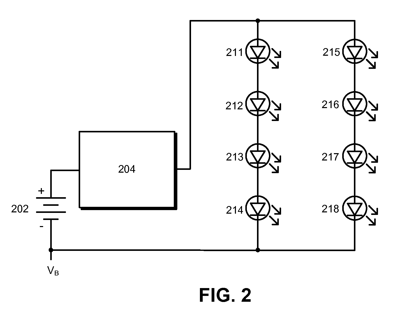
BACKGROUND[0001]1. Field[0002]The disclosed embodiments relate to power converters. More specifically, the disclosed embodiments relate to a resonant-recovery technique for reducing power consumption in boost converters.[0003]2. Related Art[0004]Power efficiency is essential for the effective operation of portable computing devices, such as laptop computers or smartphones. One source of power dissipation is the “boost converters,” which are commonly used to convert a battery voltage to higher voltage. This higher voltage can be used, for example, to power light emitting diodes (LEDs) that provide illumination for liquid crystal displays (LCDs) in portable computing devices.[0005]There are a number of contributors to power dissipation in boost converters. “Conduction losses” arise from alternating current (AC) resistances and direct current (DC) resistances in the inductor and the associated switching devices within the boost converter. Note that there exists a tradeoff between AC an...

Claims


Application Information

Patent Timeline
Patent Type & Authority Applications(United States)
IPC IPC(8): G05F1/10
CPCH02M3/1588H02M2001/0058Y02B70/1491Y02B70/1425Y02B70/1466H02M2001/346H02M1/0058H02M1/346Y02B70/10
Inventor ATHAS, WILLIAM C.UNGAR, P. JEFFREY
Owner APPLE INC
Learn More