Mixed analog-to-digital converter circuit

Active Publication Date: 2021-12-02
LONG TENG
View PDF5 Cites 0 Cited by
  • Summary
  • Abstract
  • Description
  • Claims
  • Application Information

AI Technical Summary

Benefits of technology

[0007]The technical problem to be solved by the utility model is to provide a mixed analog-to-digital converter circuit capable o

Problems solved by technology

The existing linear mode converter suffers low conversion efficiency, severe thermal issue, and low power density, therefore, the switch-mode power supply dominates the market of high power DC/DC conversion.
However, the switching actions generate square voltage/current waveforms, which cause severe instantaneous power fluctuations, and thus require bulk low-pass filters to filter ripples.
However, multi-level converters require a large number of semiconductors, and in order to maintain the power balance between sub-modules, additional sensing circuits and complex control methods are required.
However, increasing the switch frequency may increase the power loss in the semiconductor and magnetic units.
In addition, parasitic elements such as capacitors, resistors, and inductors may reduce the filtering effect of

Method used


Image

  • Mixed analog-to-digital converter circuit
  • Mixed analog-to-digital converter circuit
  • Mixed analog-to-digital converter circuit

Examples


embodiment 1

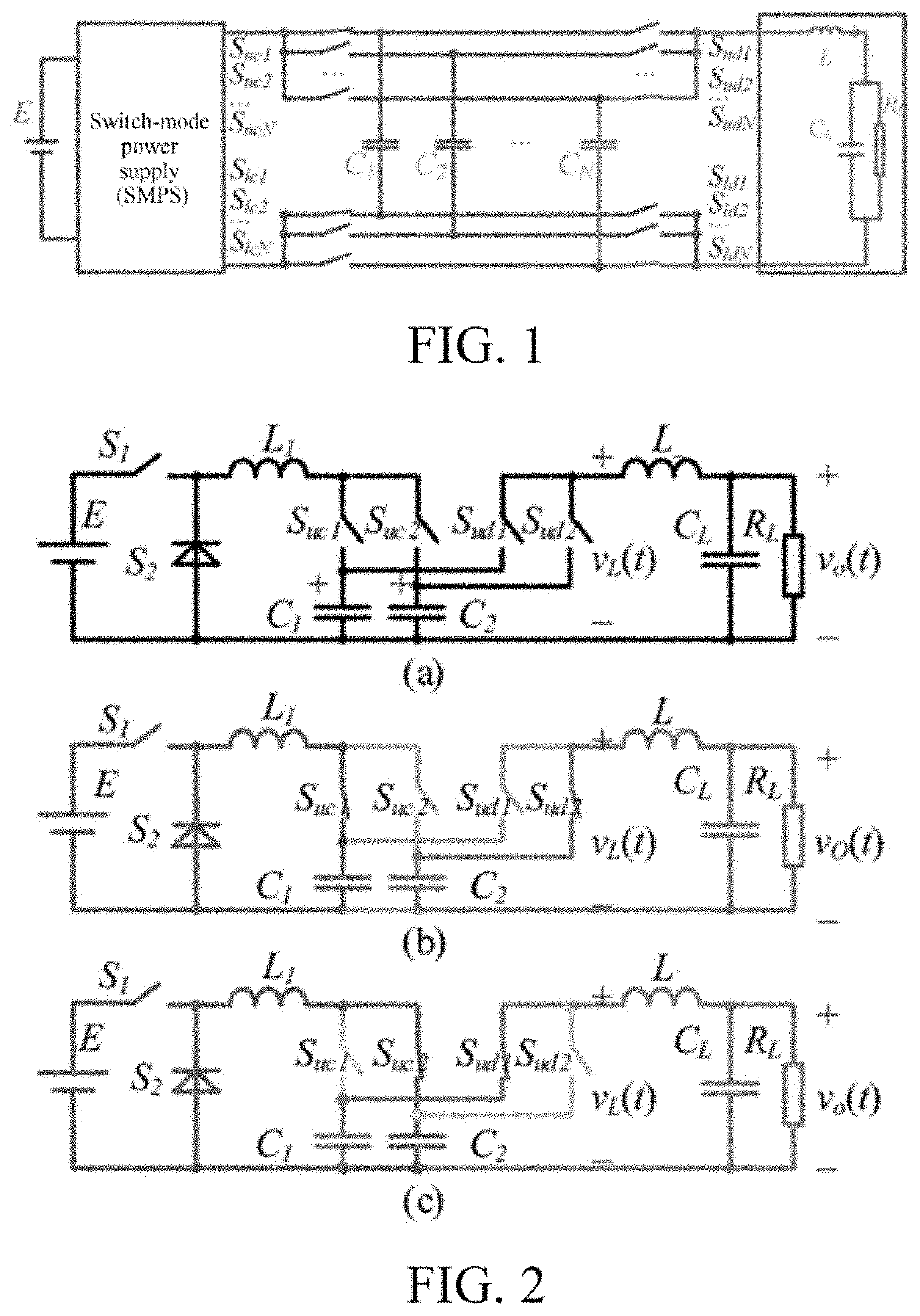
[0040 relates to, as shown in FIG. 1, a mixed analog-to-digital converter circuit, including a power supply and a digital converter connected to the power supply, where an analog converter is connected between an input end and an output end of the digital converter, and the analog converter is connected to a load assembly;

[0041]the analog converter includes a plurality of power supply capacitors; two ends of each power supply capacitor are respectively connected to the input end and the output end of the digital converter through charge wires, and two charge wires are equipped with charge switches; two ends of each power supply capacitor are respectively connected to an input end and an output end of the load assembly through discharge wires, and two discharge wires are equipped with discharge switches; when working, the load assembly is connected to corresponding power supply capacitors in turn by closing the corresponding discharge switch; and the power supply capacitors which are...

embodiment 2

[0046 relates to, as shown in FIG. 2, a mixed analog-to-digital converter circuit, including a power supply and a digital converter connected to the power supply, where the digital converter adopts a buck converter; an analog converter is connected between an input end and an output end of the digital converter; and the analog converter is connected to a load assembly;

[0047]the analog converter includes a plurality of power supply capacitors arranged in parallel; two ends of each power supply capacitor are respectively connected to the input end and the output end of the digital converter through charge wires, and one of the charge wires is equipped with a charge switch; two ends of each power supply capacitor are respectively connected to an input end and an output end of the load assembly through discharge wires, and one of the discharge wires is equipped with a discharge switch; when working, the load assembly is connected to corresponding power supply capacitors in turn by closi...

embodiment 4

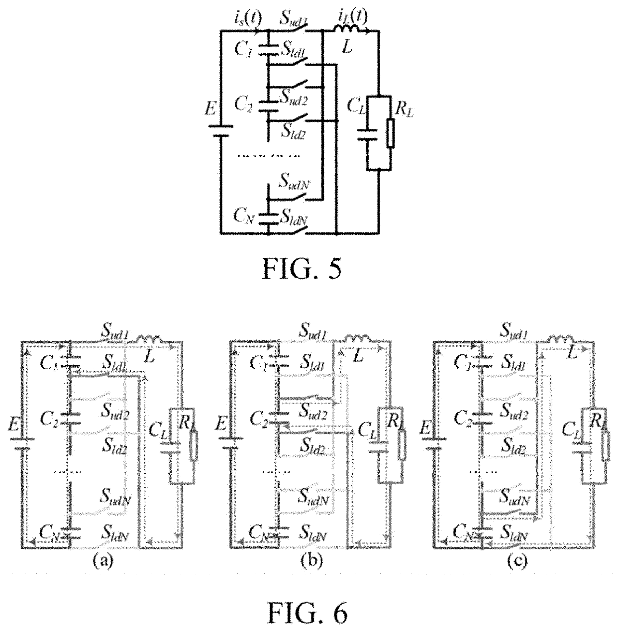
[0067 relates to a mixed analog-to-digital converter circuit, including a power supply and a digital converter connected to the power supply, where an analog converter is connected between an input end and an output end of the digital converter, and the analog converter is connected to a load assembly;

[0068]the digital converter includes a component multiplexer connected to an input end and an output end of the power supply through wires; the component multiplexer includes N power supply capacitors which are arranged in series; the analog converter includes the component multiplexer, and two ends of each power supply capacitor in the component multiplexer are respectively connected to an input end and an output end of the load assembly through discharge wires, and at least one of the discharge wires is equipped with a discharge switch; and when working, the load assembly is connected to corresponding power supply capacitors in turn by closing the corresponding discharge switch. The ...


PUM


Abstract

A mixed analog-to-digital converter circuit capable of stabilizing voltages at two ends of a load and reducing output voltage ripples, includes a power supply, a digital converter, an analog converter, and a load assembly. The analog converter includes power supply capacitors arranged in parallel; and when working, the load assembly is connected to corresponding power supply capacitors, and the power supply capacitors not connected to the load assembly are connected to the digital converter. The digital converter includes a component multiplexer connected to input and output ends of a power supply through wires; the component multiplexer includes power supply capacitors arranged in series; the analog converter includes the component multiplexer; two ends of each power supply capacitor in the component multiplexer are respectively connected to input and output ends of the load assembly through discharge wires; and when working, the load assembly is connected to corresponding power supply capacitors.

Description

BACKGROUNDTechnical Field[0001]The utility model relates to a mixed analog-to-digital converter circuit.Related Art[0002]DC / DC converters can be divided into the linear-mode and the switch-mode. The existing linear mode converter suffers low conversion efficiency, severe thermal issue, and low power density, therefore, the switch-mode power supply dominates the market of high power DC / DC conversion. The conventional switch-mode power supply is based on a digital converter and uses semiconductors as switches to control the power flow. However, the switching actions generate square voltage / current waveforms, which cause severe instantaneous power fluctuations, and thus require bulk low-pass filters to filter ripples.[0003]At present, there are mainly three methods to solve the problem of the oversize low-pass filter:[0004]The first method is to reduce the sizes of ripples from a power supply. Multi-level converters are generally used for reducing the sizes of ripples of the power supp...

Claims


Application Information

Patent Timeline
IPC IPC(8): H02M3/158H02M1/14H02M1/00
CPCH02M3/158H02M2001/0003H02M1/14H02M3/156H02M1/44H02M1/15H02M1/0003
Inventor ZHAO, HUISHEN, YANFENGLONG, TENG
Owner LONG TENG
Why Eureka
Try Eureka