Phased-array antenna and phase control method therefor

Inactive Publication Date: 2012-12-06
MITSUBISHI HEAVY IND LTD
View PDF0 Cites 8 Cited by
  • Summary
  • Abstract
  • Description
  • Claims
  • Application Information

AI Technical Summary

Benefits of technology

[0024]The present invention affords an advantage in that phase correctio

Problems solved by technology

With increasing carbon dioxide emissions due to the use of fossil fuels, environmental problems such as global warming and energy problems such as depletion of fossil fuels have been looming in recent years.
Some of the technical hurdles in implementing this scheme are high-capacity e

Method used


Image

  • Phased-array antenna and phase control method therefor
  • Phased-array antenna and phase control method therefor
  • Phased-array antenna and phase control method therefor

Examples


Example

First Embodiment

[0035]A description will be given below of an example case in which a phased-array antenna according to the present invention is applied to an SSPS.

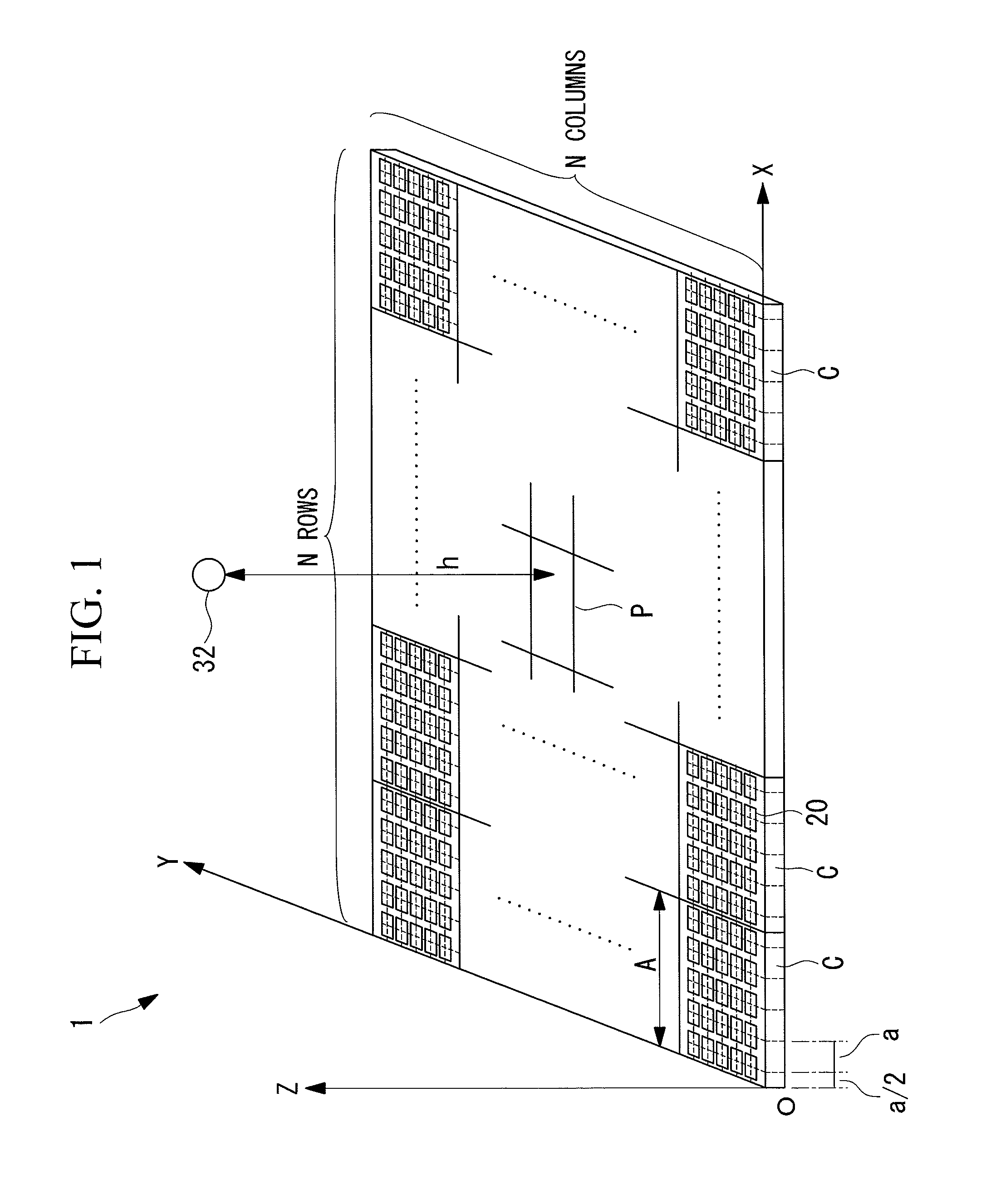
[0036]FIG. 1 is a diagram showing, in outline, the configuration of a phased-array antenna 1 according to this embodiment. As shown in FIG. 1, the phased-array antenna 1 according to this embodiment includes a plurality of antenna panels C arrayed two-dimensionally in N rows by N columns on an X-Y plane in an O-XYZ orthogonal coordinate system. Neighboring antenna panels C are joined at respective nodes (not shown). Each antenna panel C is, for example, a square of side length A (for example, about 1 m), and the phased-array antenna 1, which is large at approximately 2 km across with all panels, is constructed by joining such antenna panels C together.

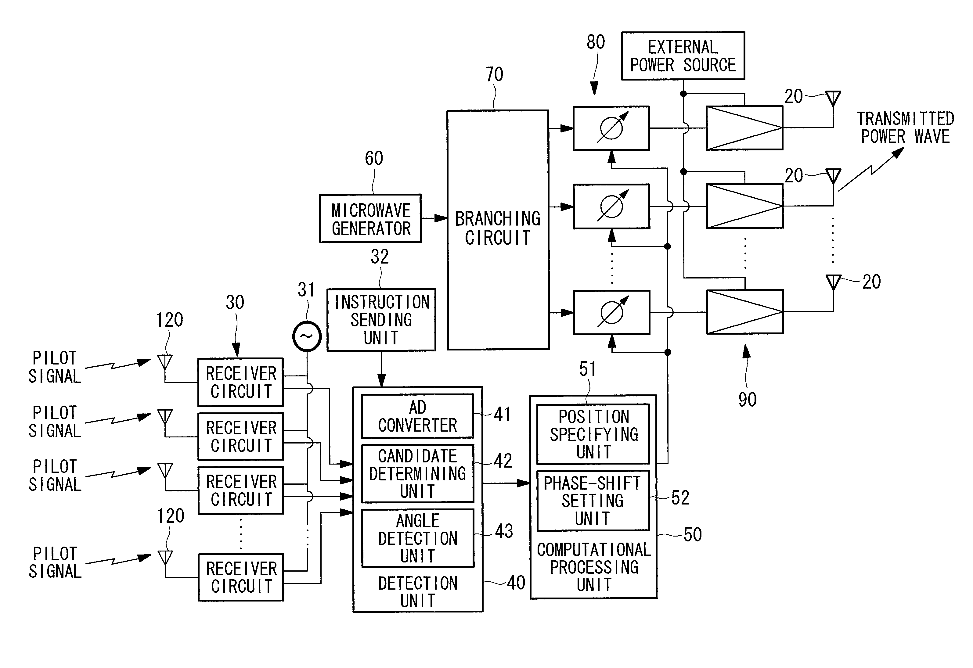
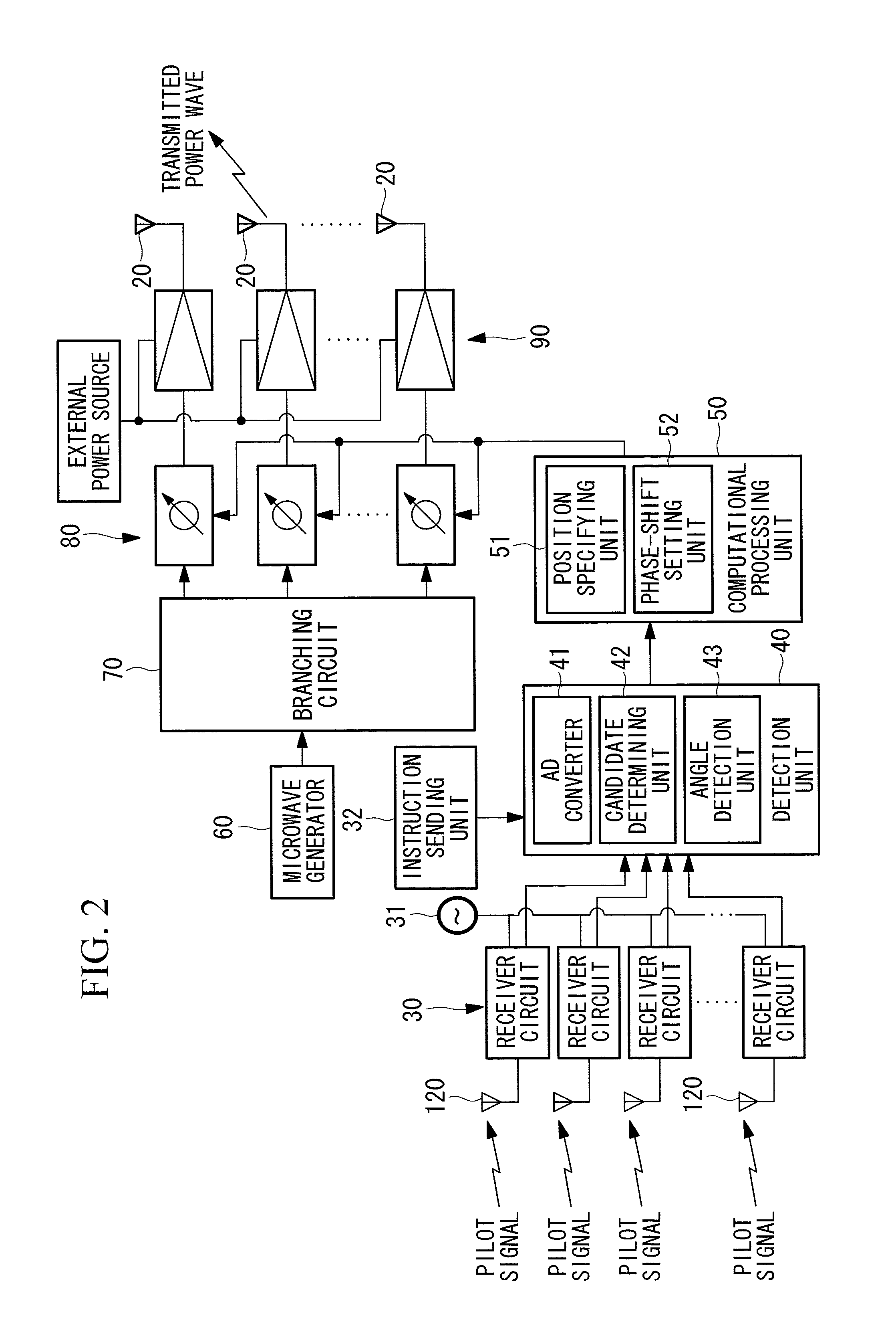
[0037]In each antenna panel C, a plurality of antenna elements 20 are two-dimensionally arrayed at predetermined intervals in the X-axis direction and the Y-axis direction. ...

Example

Second Embodiment

[0068]Next, a phased-array antenna according to a second embodiment of the present invention will be described.

[0069]The phased-array antenna according to this embodiment differs from that in the first embodiment described above in that it is further provided with a selection unit for selecting the next antenna panel for specifying the antenna panel position with the position estimating unit 51. In the following, for the phased-array antenna according to this embodiment, a description of commonalties with the first embodiment will be omitted, and mainly the differences will be described.

[0070]The selection unit (not shown in the drawings) sequentially selects a plurality of antenna panels neighboring an antenna panel whose panel position has been specified as the antenna panels whose panel positions are to be specified next. For example, in the case where each antenna panel is a quadrangle, four antenna panels neighbor each antenna panel in four directions. Here, wi...

Example

Third Embodiment

[0076]A phased-array antenna according to this embodiment differs from those in the first embodiment and the second embodiment described above in that the antenna panels are grouped into a plurality of areas, and a plurality of reference panels are provided, one for each area. In the following, for the phased-array antenna according to this embodiment, a description of commonalties with the first embodiment and the second embodiment will be omitted, and the differences will be mainly described, using FIG. 8.

[0077]In this embodiment, by way of example, a description will be given of five groups, areas A to E, which are just some of the areas formed by dividing (grouping) the phased-array antenna into a plurality of areas. In FIG. 8, the antenna panels in the phased-array antenna are grouped into a plurality of areas, and a reference panel (first reference panel) or a provisional reference panel (second reference panel) is provided in each area. In this embodiment, a r...


PUM


Abstract

The precision of phase correction is improved. Provided are a detection unit (40) that detects a phase of arrival of a pilot signal at each of antenna panel on the basis of the pilot signal and a reference signal commonly transmitted to each antenna panel; a position specifying unit (51) that specifies a position of each of the antenna panels relative to a reference panel defined as an antenna panel for reference among the plurality of the antenna panels, on the basis of the phase of arrival and an angle of arrival formed between the direction of arrival of the pilot signal and the antenna panel; and a phase-shift setting unit (52) that sets respective phase shifts for the signals radiated from individual antenna elements on the basis of information about the positions of the antenna panels specified by the position specifying unit (51).

Description

TECHNICAL FIELD[0001]The present invention relates to a phased-array antenna employed in, for example, an SSPS (Space Solar Power System), and more particularly, to a phased-array antenna that can control the beam direction of electrical power transmission to a receiving facility with high precision, and a phase control method therefor.BACKGROUND ART[0002]With increasing carbon dioxide emissions due to the use of fossil fuels, environmental problems such as global warming and energy problems such as depletion of fossil fuels have been looming in recent years. Therefore, there have been growing demands for clean energy year on year, and SSPS schemes are seen as one way of solving these problems.[0003]In an SSPS scheme, as shown in FIG. 9, an artificial satellite equipped with a gigantic solar panel is launched into equatorial orbit, and the electrical power generated from sunlight is converted into microwaves 100 by a transmitter module in the solar panel. Then, the microwaves 100 ar...

Claims


Application Information

Patent Timeline
IPC IPC(8): H01Q3/30H01Q21/06
CPCH01Q3/267H04B7/084H04B17/21H04B7/0617H04B7/086
Inventor KIMURA, TOMOHISAAMMA, KENICHIFUKUDA, NOBUHIKO
Owner MITSUBISHI HEAVY IND LTD
Why Eureka
Try Eureka