Macro Area Camera for an Infrared (IR) Microscope

a micro-area camera and infrared microscope technology, applied in the field of optical microscopy, can solve the problems of limiting the flexibility of the designer, limiting the number of apertures (na), and the inability to adjust the magnification, so as to reduce the time of video collection, facilitate the targeting of sample regions, and reduce the effect of video collection

Inactive Publication Date: 2012-12-06
THERMO ELECTRONICS SCI INSTR LLC
View PDF5 Cites 6 Cited by
  • Summary
  • Abstract
  • Description
  • Claims
  • Application Information

AI Technical Summary

Benefits of technology

[0009]The present invention is directed to an Infrared (IR) microscope that is configured with a visible camera having its optical axis collinear with the (IR) and primary visible beampath of the microscope but outside the optical path that provides the image magnification. In particular, the Infrared (IR) microscope disclosed herein includes a reflective objective configured with a primary and a secondary mirror, wherein the primary and the secondary mirror causes incoming (IR) radiation to focus at a sample plane after passing through the reflective objective to form sample induced magnified imaging and spectroscopic information and an arrayed camera as coupled to the secondary mirror provides a wide field-of-view to enable ease of targeting regions of the sample when operating the (IR) system. It is to also be appreciated that the camera's optical axis is further configured to be collinear with the optical axis of the incoming (IR) radiation but outside the optical path so as to not interfere with the incoming (IR) radiation that provides magnified imaging and spectroscopic information.
[0010]Accordingly, the present provides for the integration of a large field of view camera and illumination means (e.g., LED multi-angle illuminators) that enables: 1) the video capturing of a significantly larger area than the one provided by the objective, 2) significantly reduces the video collection time (typically one frame instead of hundreds), which also improves the overall analysis time (cost) 3) provides brighter illumination than built in Abbe or Koehler type illuminators, which helps to cover a wider range of samples with different optical and surface properties and 4) opens the simplicity of finding specimens through large field of view observation to microscopes equipped with manual stage and single / fixed objective, hence significantly reducing the implied cost.

Problems solved by technology

However, using reflective optics limits the flexibility the designer has when developing a microscope with an appropriate magnification but with a desired visible wide field-of-view for targeting desired samples and often makes variable magnification impractical.
This particular arrangement, however, has provided for a long-standing problem in the field of IR microscopy because, as known to one of ordinary skill in the art, although the visible field-of-view tends to be somewhat larger than the infrared field-of-view despite traveling through the same microscope beampath, the visible arrangement is still quite restricted by the numerical aperture (NA) and magnification of the objective.
However, this procedure also shows some inconveniences, such as: 1) the quality of the stitched, reconstructed image is subject to stage calibration and alignment accuracy to image vignetting and other illumination artifacts 2) the time required to acquire a large image composed by hundreds of frames significantly compromises the overall measurement cost per analysis 3) the illumination through the microscope objective is subject to intrinsic power of the visible light illuminators, sample reflectivity or opaqueness, etc., and 4) without the aid of a well calibrated motorized stage (i.e.; a manual stage) a large field of view image acquisition—without changing the objective magnification—is impossible.

Method used


Image

  • Macro Area Camera for an Infrared (IR) Microscope
  • Macro Area Camera for an Infrared (IR) Microscope
  • Macro Area Camera for an Infrared (IR) Microscope

Examples


Embodiment Construction

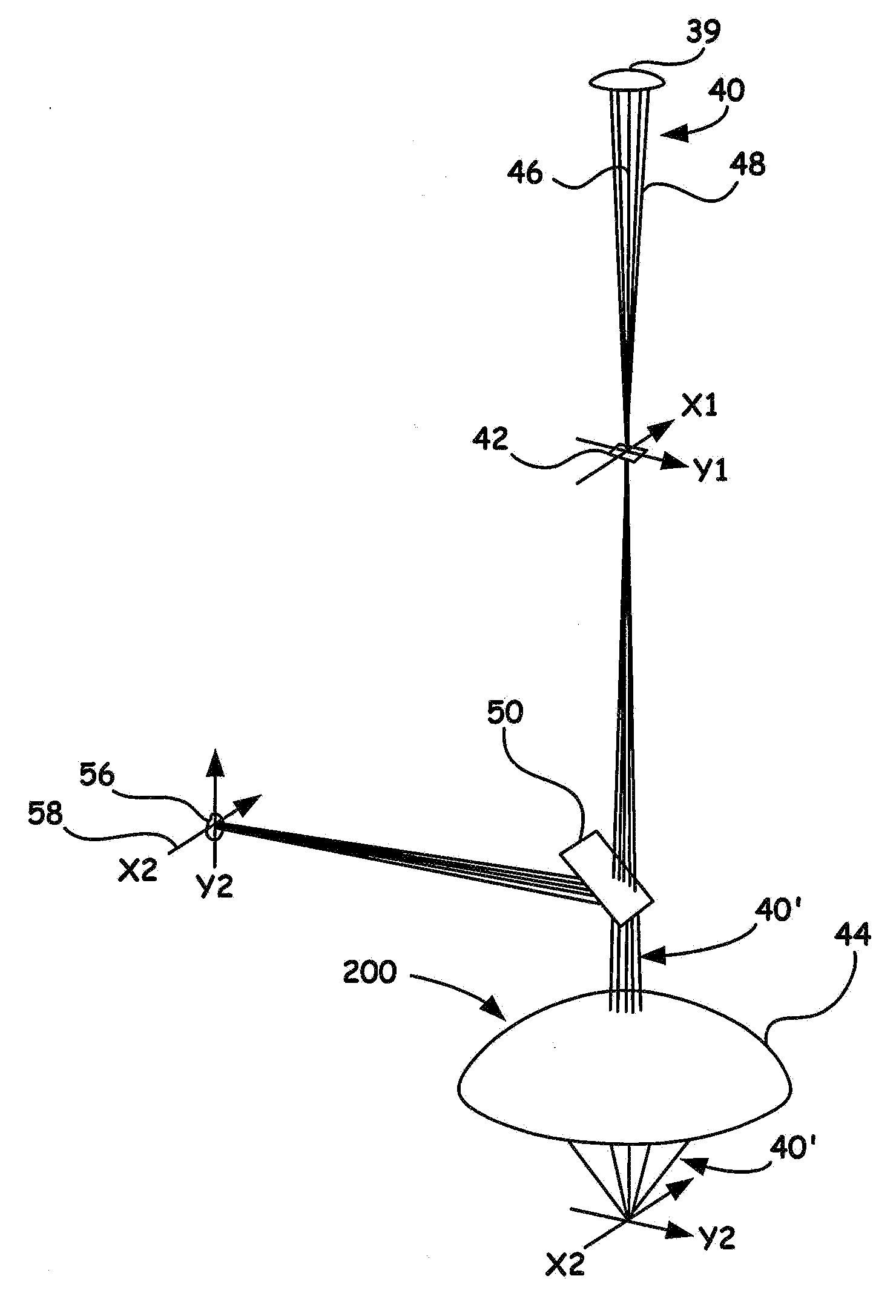
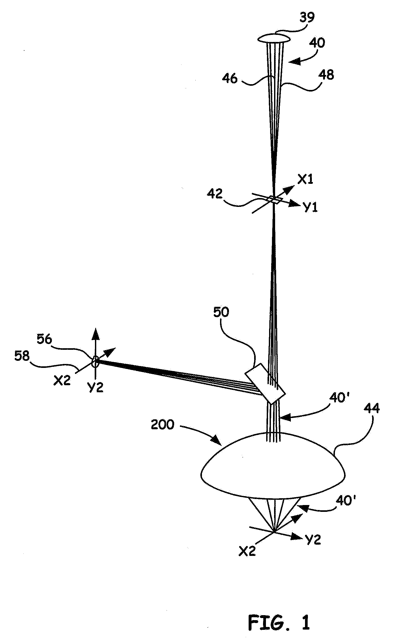
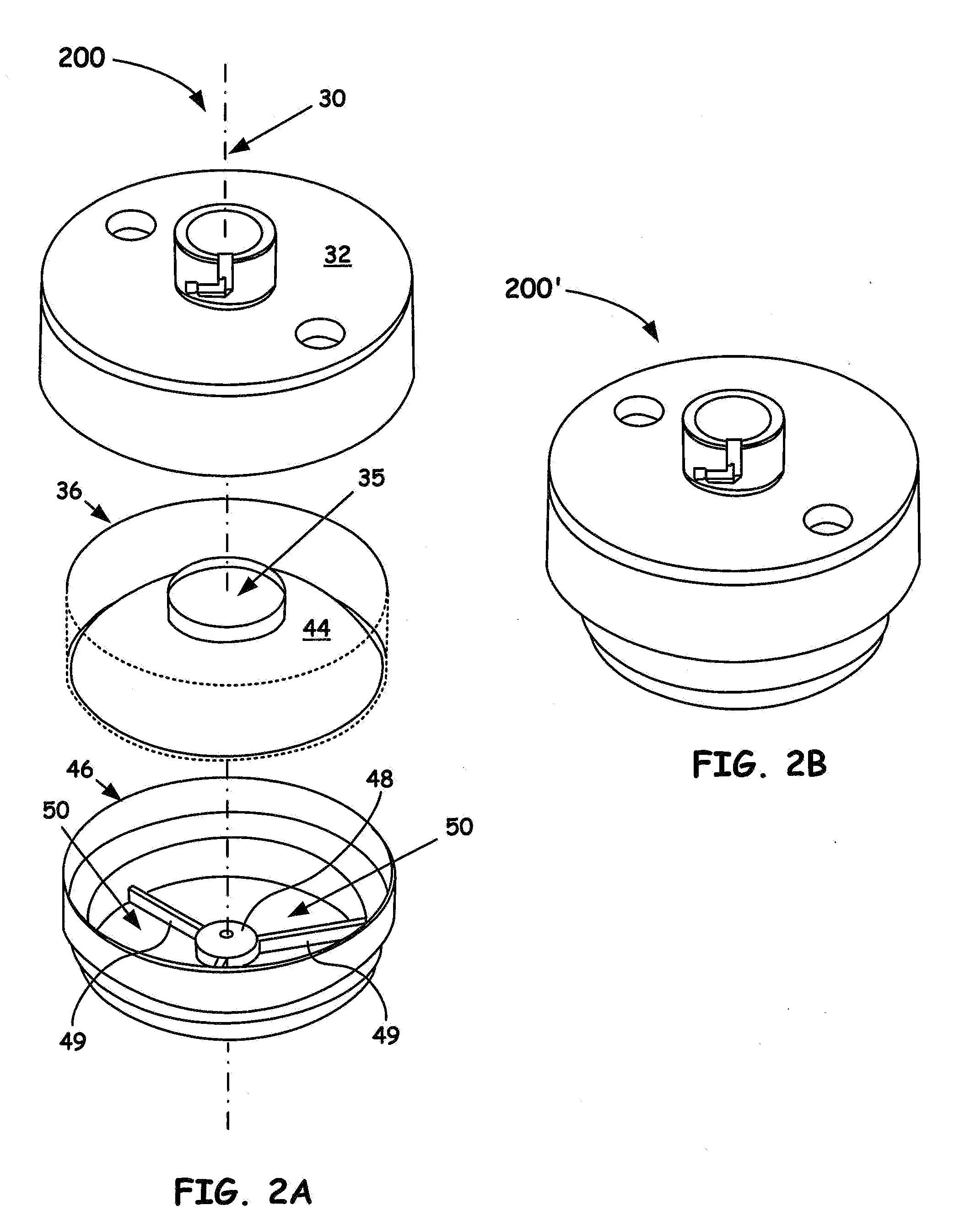
[0016]In the description of the invention herein, it is understood that a word appearing in the singular encompasses its plural counterpart, and a word appearing in the plural encompasses its singular counterpart, unless implicitly or explicitly understood or stated otherwise. Furthermore, it is understood that for any given component or embodiment described herein, any of the possible candidates or alternatives listed for that component may generally be used individually or in combination with one another, unless implicitly or explicitly understood or stated otherwise. Moreover, it is to be appreciated that the figures, as shown herein, are not necessarily drawn to scale, wherein some of the elements may be drawn merely for clarity of the invention. Also, reference numerals may be repeated among the various figures to show corresponding or analogous elements. Additionally, it will be understood that any list of such candidates or alternatives is merely illustrative, not limiting, u...


PUM


Abstract

A novel arrangement of Schwarzschild Cassegrainian objective coupled with a far-field visible imaging system that does not interfere with the interrogating (IR) beam is introduced. Typical (IR) microscopes that incorporate a Cassegrainian objective have difficulty in locating desired target sample regions based on the inherent limited field-of-view. Because commonly applied visible imaging accessories upstream must use the same numerical aperture based on the reflective geometry, such systems also suffer a limited field of view. To overcome such difficulties, the novel embodiments herein involve placing a visible camera with its optical axis collinear with the IR and primary visible beampath of the microscope but outside the optical path that provides the (IR) image magnification.

Description

BACKGROUND OF THE INVENTION[0001]1. Field of the Invention[0002]The present invention relates to the field of optical microscopy. More particularly, the present invention relates to a novel reflective infrared microscope objective that enables simultaneous viewing of both, the area of interest and a significantly wider field of view.[0003]2. Discussion of the Related Art[0004]Infrared (IR) and in particular Fourier Transform infrared (FTIR) microscope systems enable optical spectroscopic interrogation of substantially small samples (e.g., areas of about 25 μm×25 μm) by mapping the acquired image data of a larger area of a sample with a defined spatial resolution. Accordingly, a beneficial aspect of the FTIR microscope is the ability to collect infrared spectra from a much smaller, defined area of the sample matrix. FTIR microscopy in particular can provide spectral information of a very small contaminant embedded in a sample or particular details regarding chemical constituents or o...

Claims


Application Information

Patent Timeline
Patent Type & Authority Applications(United States)
IPC IPC(8): H04N7/00
CPCG02B21/0004G01J3/0208G02B21/362H04N23/11
Inventor MERRILL II, DENNIS E.IZZIA, FEDERICO
Owner THERMO ELECTRONICS SCI INSTR LLC
Why Eureka
Try Eureka