[0010]According to this, the object of the present invention is the creation of a wear-free, reliable drive device—suitable for fast, smaller adjustments—for temperature-independent adjustment of the vanes which extend radially in an annular passage and are rotatable around their respective longitudinal axis.
[0015]In addition to the compact and light-weight construction on account of using a larger number of motors, a further
advantage lies in the greater adjustment speed which the drive device now enables for the first time. The transmission of force from the motors to the directly driven vanes is carried out without backlash and to the remaining vanes almost without backlash. In conjunction with the compact construction and the comparatively low masses which are to be moved, the vanes can also be adjusted by comparatively small angle values in a comparatively short time. The known gear drives, however, always provide that all the vanes are driven indirectly via the adjustment ring.
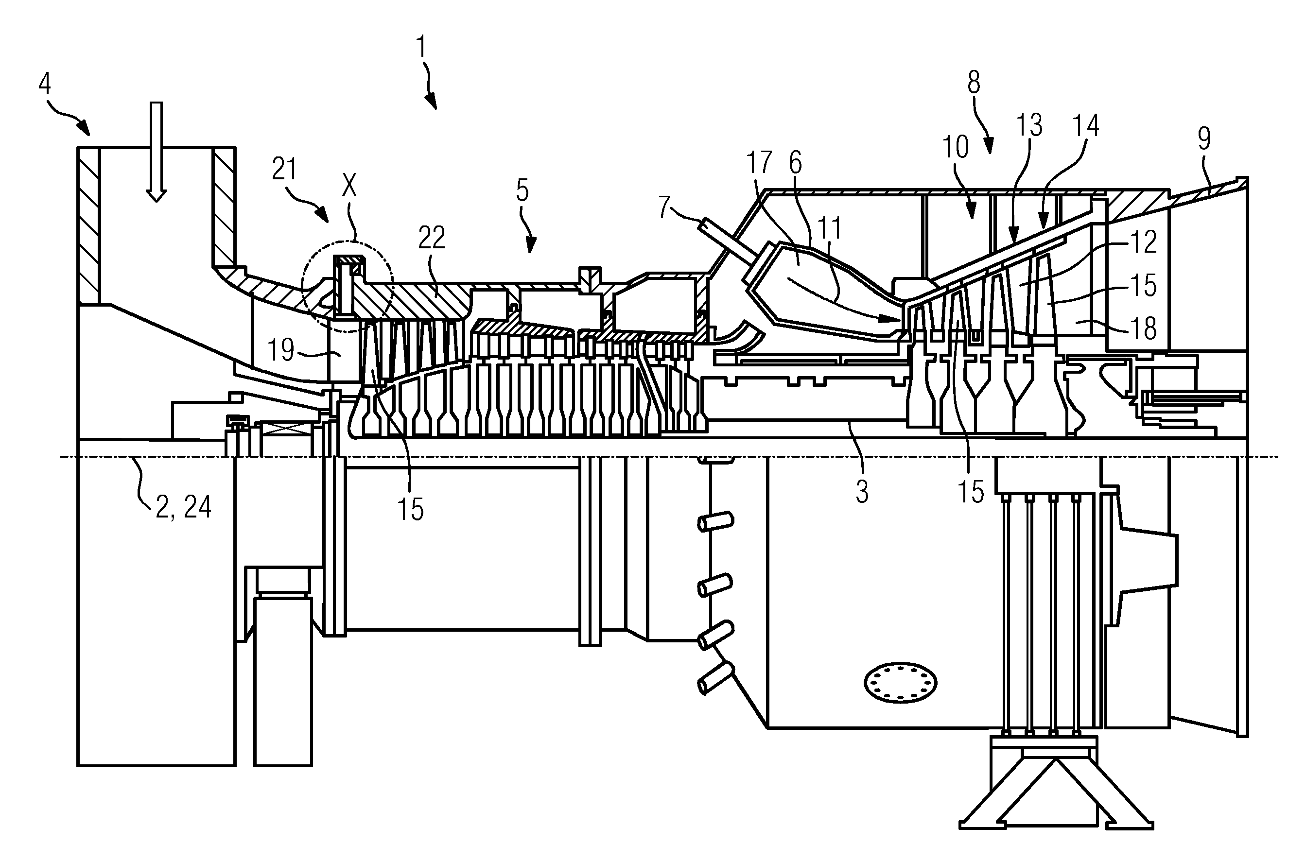
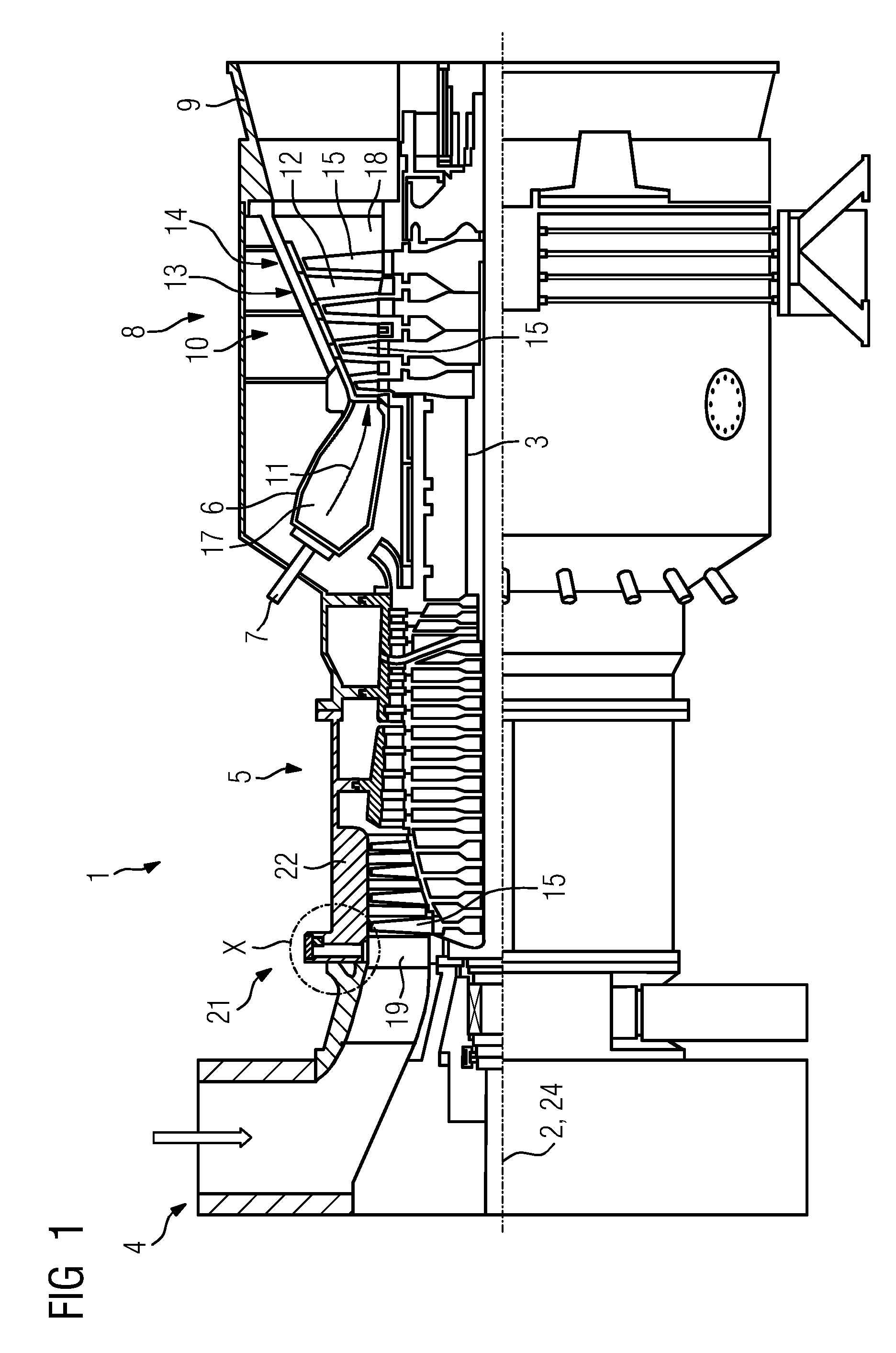
[0020]According to a further advantageous development, provision is made in the vane carrier or in the casing encompassing the vane carrier for a circumferential groove on the generated surface side, in which the pivot pins end and in which the adjustment ring is arranged, wherein for the shielding of pivot pins, adjustment ring and their
coupling the circumferential groove is closed off to the outside at least for the most part by means of a cover. The
coupling of adjustment ring and pivot pin is therefore embedded in the vane carrier or recessed in the circumferential groove, as a result of which a two-sided shielding is created, as seen in the longitudinal direction of the turbomachine. With this advantageous embodiment, it departs from the prior art in which the adjustment mechanism was previously arranged outside the casing of the turbomachine without protection. It is now provided that the adjustment mechanism is at least covered, if not even hermetically sealed, as a result of which the drive for the most part (that is to say except for the lead-through for the
drive shaft of the motor) is relocated into the wall of the vane carrier. This requires that the vane carrier, in the region in which the pivot pins project into it, is of at least such thickness there that a circumferential groove for accommodating the pivot pin ends and the adjustment ring can be introduced there from the outside, for example by means of mechanical
machining. The covering of the circumferential groove by means of a plurality of cover segments is simple to achieve in this case, wherein the fastening of the cover, or cover elements, can be carried out by conventional means, such as by screws. A simple construction, which can be comparatively simply and also inexpensively realized, can be realized with this.
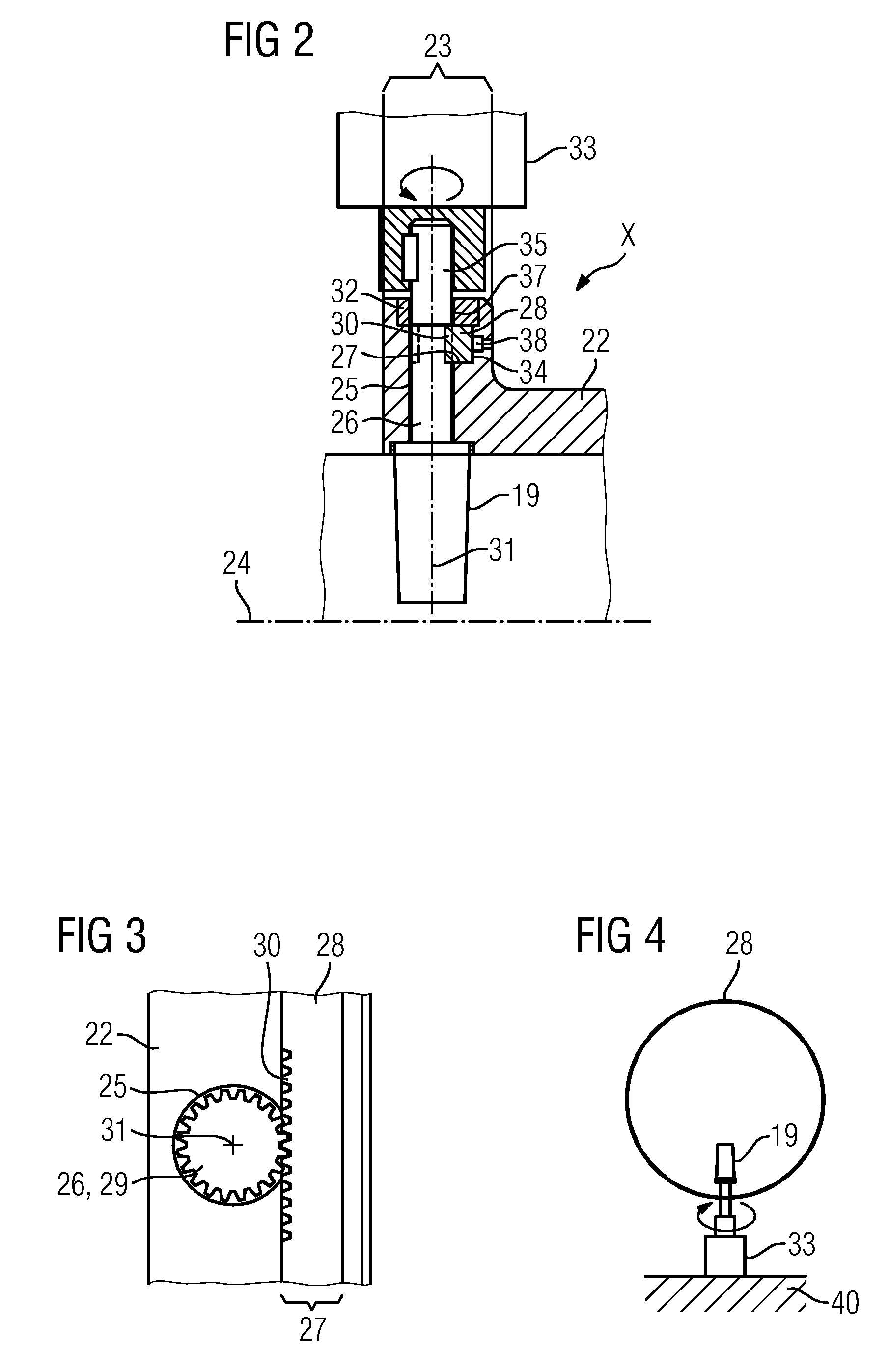
[0022]An especially simple and reliable supporting of the adjustment ring can be achieved if this—with regard to the center axis of the vane carrier—is guided radially on the outside by the cover of the circumferential groove and radially on the inside by the groove base of the circumferential groove. The cover then also serves as a guide for the adjustment ring since this bears in a slidable, but clearance-free, manner both on the cover and on the groove base. This avoids the use of additional construction elements such as support rollers for the central supporting of the adjustment ring in relation to the
machine axis. This embodiment also enables a comparatively thin adjustment ring since its natural rigidity can now be lower than previously.
[0024]In order to prevent gaping of the toothing, the adjustment ring is axially guided by a sidewall of the circumferential groove, with regard to the center line of the vane carrier. Alternatively or in addition thereto, it can be provided that means for pressing the adjustment ring onto the pivot pins are provided in the sidewall or between sidewall and adjustment ring. For example, passages for the feed of a hydraulic medium can open into the sidewall for this purpose. It is also possible that provision is made between the sidewall and the adjustment ring for spring elements, also uniformly distributed over the circumference, which exert an axially acting force upon the adjustment ring. As a result of using a toothing arrangement, the adjustment ring can be of thinner design than the comparatively
solid adjustment ring from the prior art for stationary
gas turbines. By pressing the adjustment ring onto the pivot pins, the
elimination of the tooth flank clearance can also be carried out in order to thus keep the adjustable vanes free from play in their predetermined position during operation of the turbomachine. If necessary, the pressing-on force can be reduced during the adjustment process, which is easily possible especially when a hydraulic medium is being used as the pressing-on means. In this case, the adjustment process can be accomplished with comparatively small forces.

