Dual injection airlift pump

a technology of airlift pump and air pump body, which is applied in the direction of pump components, machines/engines, pressure exchangers, etc., can solve the problems of not producing high pressure heads, entrain the majority of liquid in the pump body so as to reduce hydrodynamic friction, increase efficiency, and add buoyancy

Inactive Publication Date: 2012-12-06
KING FAHD UNIVERSITY OF PETROLEUM AND MINERALS
View PDF8 Cites 7 Cited by
  • Summary
  • Abstract
  • Description
  • Claims
  • Application Information

AI Technical Summary

Benefits of technology

[0008]The lower portion includes an inner sleeve having a large number of radial passages therethrough, the air or gas passing through these passages in the sleeve in a radial direction to be distributed symmetrically through the liquid within the lower portion of the pump. The upper portion includes an impervious inner sleeve sealed to the pump wall at its lower end and open at its upper end. Air is injected through passages in the pump wall to flow in an axial direction between the pump wall and the impervious sleeve, where the air escapes through the open gap between the pump wall and the upper end of the sleeve. This axial peripher

Problems solved by technology

Pumps operating by this principle do not produce high pressure heads, but are capable of moving volumes of liquid reasonably efficiently with relatively low energy input.
The provision of only a single point discharge for the air

Method used


Image

  • Dual injection airlift pump
  • Dual injection airlift pump
  • Dual injection airlift pump

Examples


Embodiment Construction

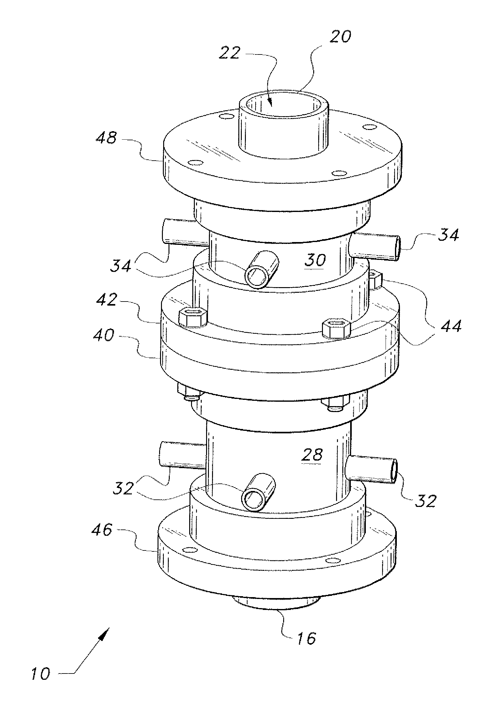
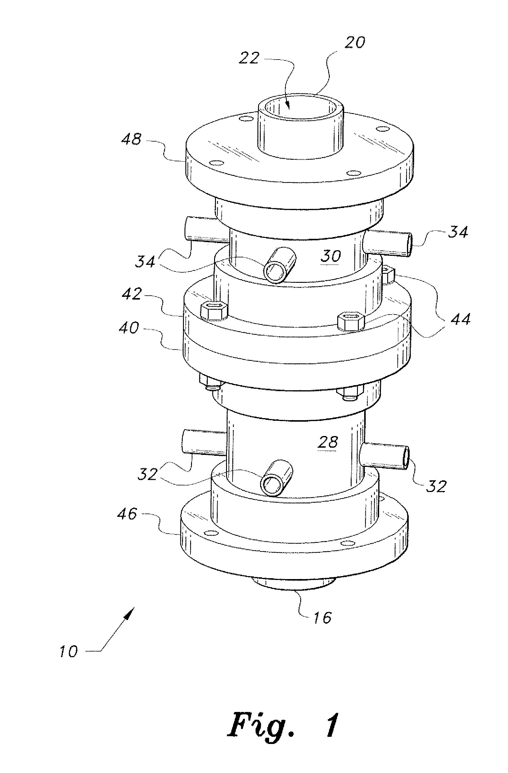
[0014]The dual injection airlift pump is a dual stage device having two levels or stages of air or other gas input to the pump body. One level or stage delivers the air or other gas radially into the liquid flow passage, and the other level or stage delivers the air or other gas into the liquid flow passage via an axially peripheral path for increased efficiency. The dual injection airlift pump may use air as the liquid entraining gas, or some other gas (e.g., nitrogen, carbon dioxide, helium, etc.) as the liquid-entraining-gas, if desired. It will be understood in the following disclosure that the terms “air” and “gas” may be used interchangeably when referring to the air or gas used to entrain and add buoyancy to the liquid stream (e.g., water, oil, or other liquid) passing through the pump.

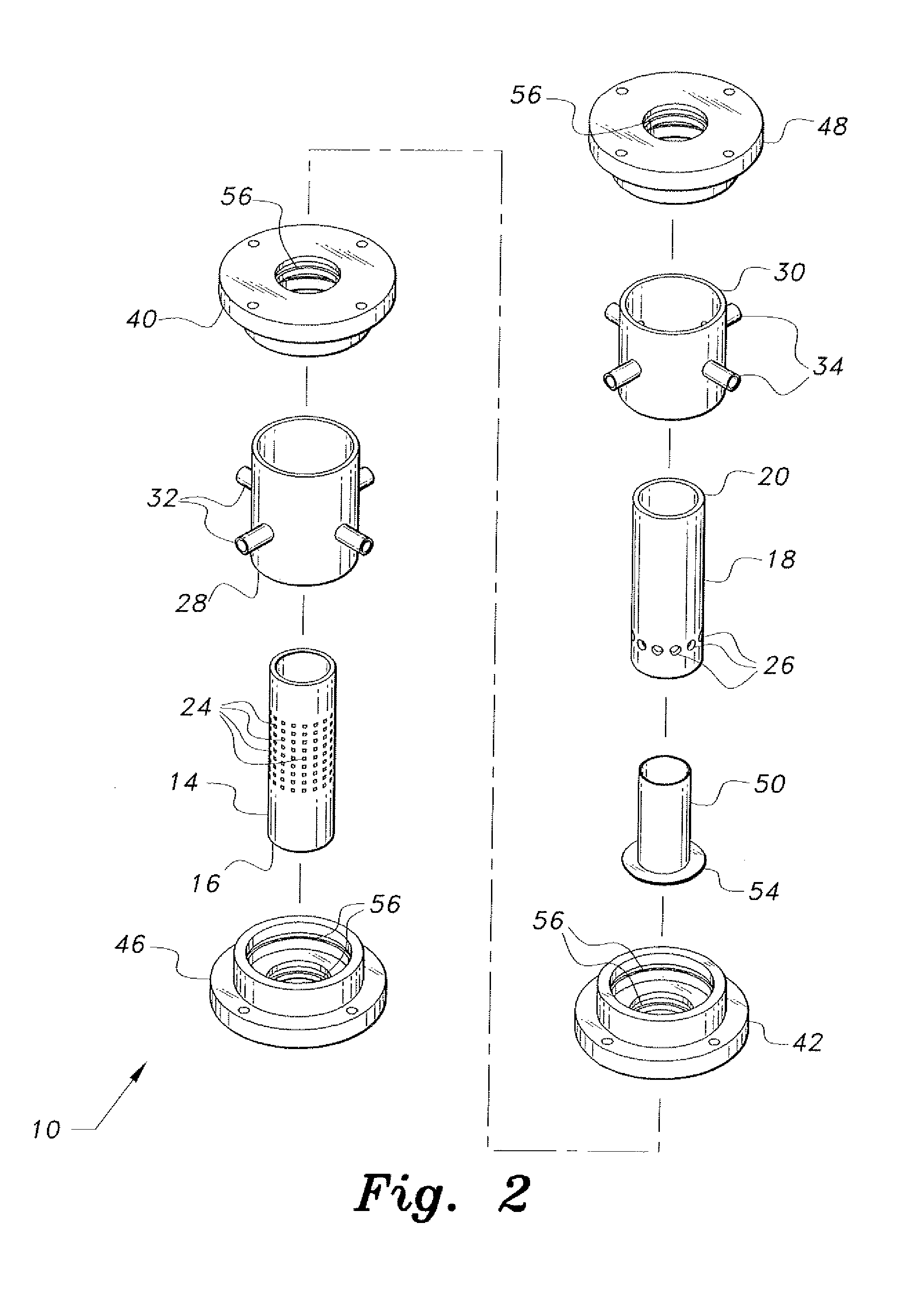
[0015]FIG. 1 of the drawings is an illustration of an exemplary dual injection airlift pump 10 according to the present invention. FIG. 2 illustrates the various components of the pump 10 (conn...


PUM


Abstract

The dual injection airlift pump has a hollow tubular body through which the liquid being pumped passes upward from the lower intake end to the upper outlet end. Air or other gas is injected into the liquid in the pump body, the less dense gas adding buoyancy to the liquid and entraining the liquid to rise toward the outlet end. The dual injection airlift pump includes two air injection stages, with the first or lower stage having a perforated interior sleeve allowing the gas to pass therethrough to be injected radially into the liquid. The second, upper stage has an impervious sleeve defining a gap between the sleeve and the interior surface of the pump wall, the lower end being sealed and the upper end open. Air is injected between the sleeve and pump wall, the air exiting at the upper or downstream end in an axially peripheral flow pattern.

Description

BACKGROUND OF THE INVENTION[0001]1. Field of the Invention[0002]The present invention relates to fluid transfer devices, and more particularly to a dual injection airlift pump having both radial and axially peripheral air or gas injection.[0003]2. Description of the Related Art[0004]The general concept of the airlift pump has been known for quite some time. Airlift pumps generally comprise a vertically oriented tubular pump body through which the liquid that is being pumped passes. One or more air (or other gas) injection passages are provided in or with the pump body. The airlift pump contains no moving parts, but rather depends upon the injection of air (or other gas) into the pump interior to lift a liquid passing through the pump. The lighter air or gas bubbles upwardly through the liquid in the tubular pump body, increasing the buoyancy of the liquid and causing it to rise in the vertically oriented tubular body. Pumps operating by this principle do not produce high pressure he...

Claims


Application Information

Patent Timeline
IPC IPC(8): F04F1/06
CPCF04F1/06
Inventor BADR, HASSAN MOHAMEDAHMED, WAEL HASAN
Owner KING FAHD UNIVERSITY OF PETROLEUM AND MINERALS
Why Eureka
Try Eureka