Flowing electrolyte reservoir system

a technology of electrolyte reservoir and flow system, which is applied in the direction of secondary cell details, sustainable manufacturing/processing, indirect fuel cells, etc., can solve the problems of lead-acid batteries that have limitations in terms of performance and environmental safety, lead-acid batteries are also environmentally hazardous, and typical lead-acid batteries have very short lifetimes in hot climate conditions. , to achieve the effect of improving structural robustness of electrolyte tanks, reducing manufacturing costs, and increasing safety

Inactive Publication Date: 2012-12-06
REDFLOW PTY LTD
View PDF5 Cites 11 Cited by
  • Summary
  • Abstract
  • Description
  • Claims
  • Application Information

AI Technical Summary

Benefits of technology

[0010]Therefore, an object of the present invention is to overcome or alleviate one or more limitations of the prior art including providing improved flowing electrolyte reservoir systems for circulating electrolyte through a battery cell stack, to reduce manufacturing costs, increase safety and improve structural robustness of electrolyte tanks, and reduce tank size and weight.SUMMARY OF THE INVENTION

Problems solved by technology

However, lead-acid batteries have limitations in terms of performance and environmental safety.
For example, typical lead-acid batteries often have very short lifetimes in hot climate conditions, especially when they are occasionally fully discharged.
Lead-acid batteries are also environmentally hazardous, since lead is a major component of lead-acid batteries and can cause serious environmental problems during manufacturing and disposal.
However, such conventional shapes and arrangements of electrolyte storage tanks can cause numerous problems, including safety concerns related to leaking electrolyte, excessive plumbing costs, wasted materials, high manufacturing costs, and over-sized systems.

Method used


Image

  • Flowing electrolyte reservoir system
  • Flowing electrolyte reservoir system
  • Flowing electrolyte reservoir system

Examples


Embodiment Construction

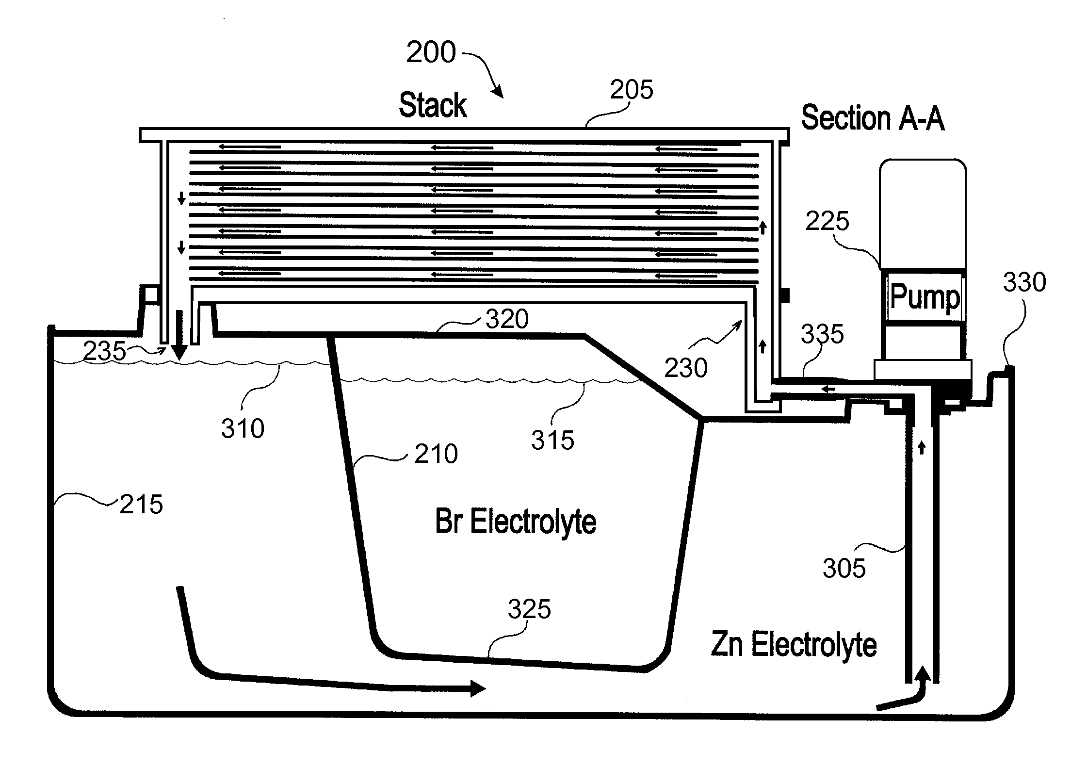
[0038]Embodiments of the present invention comprise a cell stack for a flowing electrolyte battery. Elements of the invention are illustrated in concise outline form in the drawings, showing only those specific details that are necessary to understanding the embodiments of the present invention, but so as not to clutter the disclosure with excessive detail that will be obvious to those of ordinary skill in the art in light of the present description.

[0039]In this patent specification, adjectives such as first and second, left and right, front and back, top and bottom, etc., are used solely to define one element or method step from another element or method step without necessarily requiring a specific relative position or sequence that is described by the adjectives. Words such as “comprises” or “includes” are not used to define an exclusive set of elements or method steps. Rather, such words merely define a minimum set of elements or method steps included in a particular embodiment...


PUM

PropertyMeasurementUnit
weight ratioaaaaaaaaaa
total voltageaaaaaaaaaa
vapour pressureaaaaaaaaaa

Abstract

A flowing electrolyte reservoir system for a flowing electrolyte battery. The system comprises an outer electrolyte tank and an inner electrolyte tank placed under a battery cell stack. The inner tank is transversely positioned between opposite corners of the outer electrolyte tank, and beneath opposite corners of the battery cell stack.

Description

FIELD OF THE INVENTION[0001]The present invention relates to flowing electrolyte batteries. In particular, although not exclusively, the invention relates to a flowing electrolyte reservoir system having a tank within a tank.BACKGROUND TO THE INVENTION[0002]Batteries used in stand alone power supply systems are commonly lead-acid batteries. However, lead-acid batteries have limitations in terms of performance and environmental safety. For example, typical lead-acid batteries often have very short lifetimes in hot climate conditions, especially when they are occasionally fully discharged. Lead-acid batteries are also environmentally hazardous, since lead is a major component of lead-acid batteries and can cause serious environmental problems during manufacturing and disposal.[0003]Flowing electrolyte batteries, such as zinc-bromine batteries, zinc-chlorine batteries, and vanadium flow batteries, offer a potential to overcome the above mentioned limitations of lead-acid batteries. In ...

Claims


Application Information

Patent Timeline
Patent Type & Authority Applications(United States)
IPC IPC(8): H01M10/02H01M10/50H01M2/02H01M50/77
CPCH01M8/188H01M8/20H01M10/365H01M2/40Y02E60/528Y02E60/50Y02E60/10H01M50/77Y02P70/50
Inventor WINTER, ALEXANDER RUDOLF
Owner REDFLOW PTY LTD
Why Eureka
Try Eureka