
Common communications device

a communication device and common technology, applied in the field of common communication devices, can solve the problems of cable connection clumsiness, potential electrical shock hazards, trip hazards, etc., and achieve the effect of increasing the bandwidth

Active Publication Date: 2012-12-06
OXFORD UNIV INNOVATION LTD
View PDF3 Cites 6 Cited by
  • Summary
  • Abstract
  • Description
  • Claims
  • Application Information

AI Technical Summary

Benefits of technology

[0009]Embodiments of the invention have the advantage that input and output devices may be coupled to one another by means of a common communications device at substantially any position of the device. Furthermore, more than two devices can be coupled to the device without a requirement to provide connectors and associated switching electronics.
[0015]This has the advantage that devices exploiting MI waves in the near-field regime may be arranged not to emit electromagnetic radiation in the far-field regime, thereby eliminating a requirement for licensing considerations in respect of electromagnetic spectrum transmission bands. Furthermore, shielding may be added if desired, although it is envisaged to be unnecessary in most implementations.
[0016]Furthermore, bandwidth can be increased by raising the frequency of operation, the limit to frequency of operation being set by fabrication issues and the complex conductivity of metallic conductors used (of the order of 100 s of GHz).
[0039]This has the advantage that an ease with which an unauthorised party may couple a resonant element to the device may be reduced.
[0041]This has the advantage that in some cases if an unauthorised party seeks to couple a resonant element to the device the device may be caused to become disabled. The device may be arranged to be caused to become permanently disabled (a one-shot arrangement). Alternatively the device may be arranged to be caused to become reversibly disabled.

Problems solved by technology

A problem associated with cable connections is that they present a trip hazard as well as a potential electrical shock hazard.
Cable connections are also potentially clumsy and require manual manipulation of a connector fitted to the cable in order to effect a connection.
This can be a problem for physically challenged individuals.
Repeated connection and disconnection limits the lifespan of connectors due to wear.

Method used


Image

  • Common communications device
  • Common communications device
  • Common communications device

Examples


Embodiment Construction

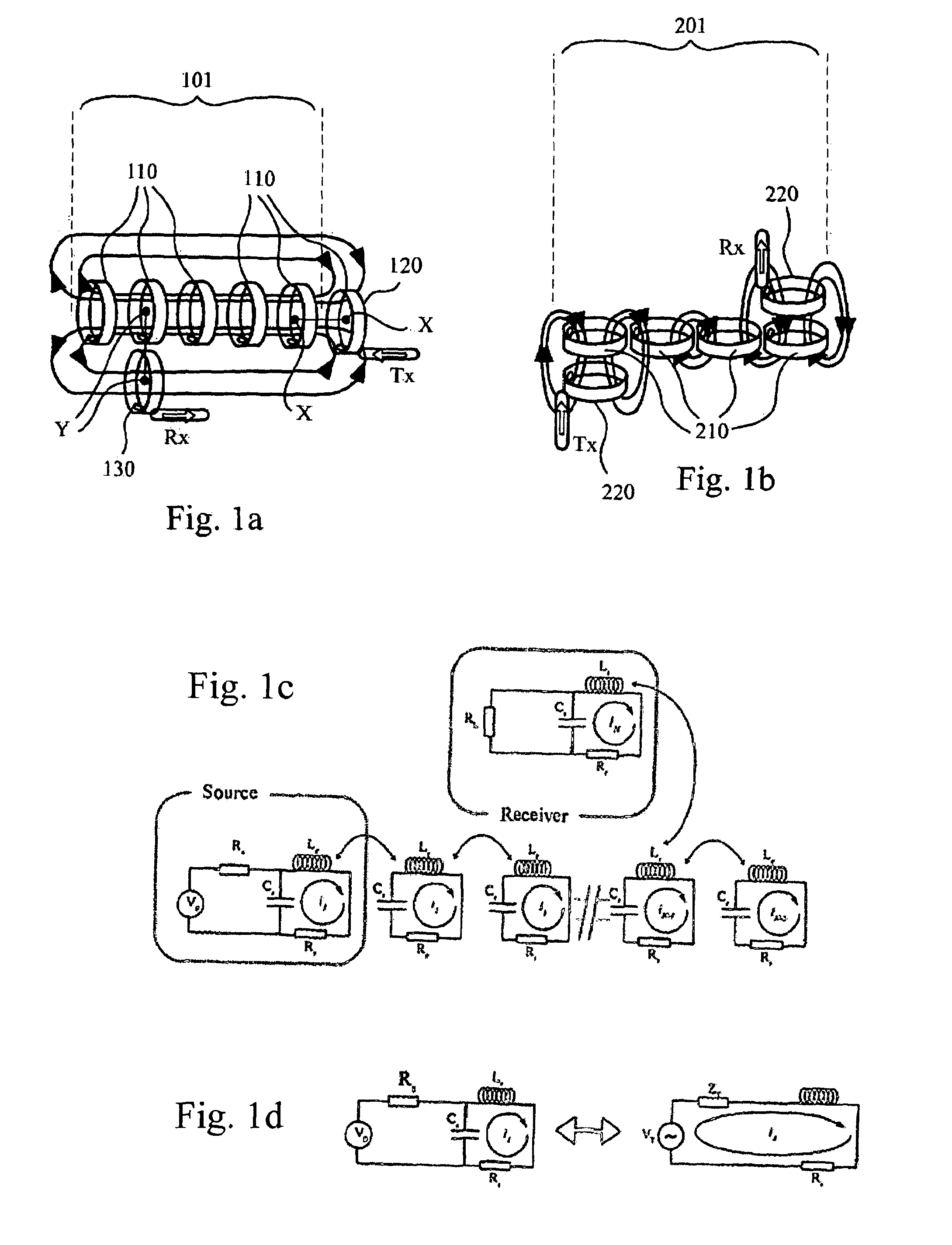
[0073]FIG. 1 shows (a) an array 101 of axially-coupled resonant circuits 110 and (b) an array 201 of plane-coupled resonant circuits 210 providing a common communications device (or channel) according to an embodiment of the invention. The circuits 110, 210 are arranged to be coupled together by means of magnetic flux generated by electric currents induced in loop portions of respective circuits 110, 210.

[0074]In FIG. 1(a) a resonant circuit 120 of a transmitter unit is shown axially-coupled to the array 101 of resonant circuits 110 whilst a resonant circuit 130 of a receiver unit is shown plane-coupled to the array 101.

[0075]By axial coupling between a pair of resonant circuits is meant that a nominal line connecting a centre of each loop of the pair of resonant circuits has at least a non-negligible component parallel to a normal to a plane of the loop as shown in the case of line X-X of FIG. 1(a).

[0076]By plane or planar coupling between a pair of resonant circuits is meant that ...


PUM


Abstract

A common communications device comprising an array of near-field coupled resonant elements, the elements each comprising a coupling portion comprising a loop portion with free ends, the device being provided in combination with a data transmission unit and a data reception unit, each unit having a coupling portion, the units being arranged to communicate with one another by means of the coupling portion of each unit and the common communications device, the coupling portion of the data transmission unit comprising a resonant element comprising a loop portion arranged to be near-field coupled to the loop portion of a first resonant element of the device, the coupling portion of the data reception unit comprising a resonant element comprising a loop portion arranged to be near-field coupled to the loop portion of a second resonant element of the device not being the first resonant element.

Description

FIELD OF THE INVENTION[0001]The present invention relates to communications devices. In particular the invention relates to a common communications device by means of which data may be transmitted between electronic devices.BACKGROUND[0002]Data connections between electronic devices are typically made by means of cables or by wireless radio communications devices. Computing devices typically connect with associated accessories and peripherals such as printers, digital cameras, external hard drives and flash drives by Universal Serial Bus (USB) or similar cable interfaces. Wireless communications devices are also common. Microprocessors are generally connected to associated components via multiconductor bus lines defined as tracks on a printed circuit board (PCB) or similar.[0003]A problem associated with cable connections is that they present a trip hazard as well as a potential electrical shock hazard. Thus, cable management systems are typically required. Such systems are particul...

Claims


Application Information

Patent Timeline
IPC IPC(8): H01Q21/00H04B5/02
CPCH01P1/20381H04B5/0012H04B5/0081H04B5/0037H04B5/0031Y02T90/16Y04S30/14B60L53/65Y02T90/167H04B5/22H04B5/72H04B5/26H04B5/79H04B5/00H01P3/00Y02T10/7072Y02T90/14Y02T10/70Y02T90/12
Inventor EDWARDS, DAVID JOHNSTEVENS, CHRISTOPHER JOHNSHAMONINA, EKATERINASOLYMAR, LASZLO
Owner OXFORD UNIV INNOVATION LTD
Learn More