Manufacturing method of a heat conductive device for a light-emitting diode

a technology of heat conductive devices and light-emitting diodes, which is applied in the direction of heat exchanger fastening, semiconductor devices for light sources, light-emitting devices, etc., can solve the problems of unsatisfactory heat dissipation efficiency, increased temperature of led lamps, and improper operation of led lamps, so as to achieve the effect of enhancing heat conduction efficiency

Inactive Publication Date: 2012-12-13
PAN JIT INT
View PDF10 Cites 9 Cited by
  • Summary
  • Abstract
  • Description
  • Claims
  • Application Information

AI Technical Summary

Benefits of technology

[0006]An objective of the present invention is to provide a forming method of a heat conducti...

Problems solved by technology

As the foregoing LED carrier only employs the single heat-conducting surface formed on the top surface of the LED carrier, the heat-conducting surface is not large enough, the heat-conducting surface and the heat sink are fastened by bolts, lots of air gaps exist between the heat-conducting surface and the heat sink and heat generated by the LED lamp fails to ...

Method used


Image

  • Manufacturing method of a heat conductive device for a light-emitting diode
  • Manufacturing method of a heat conductive device for a light-emitting diode
  • Manufacturing method of a heat conductive device for a light-emitting diode

Examples


Embodiment Construction

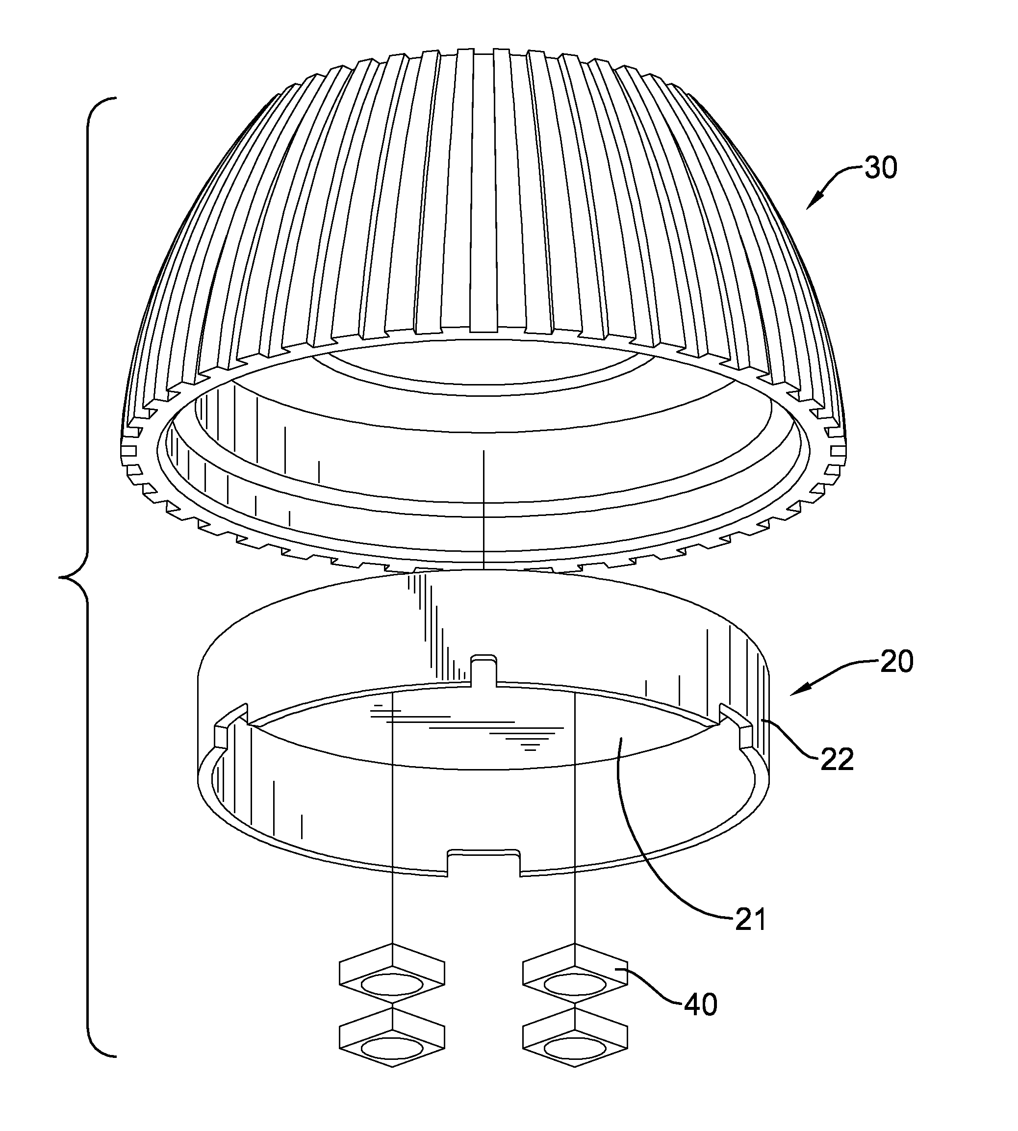
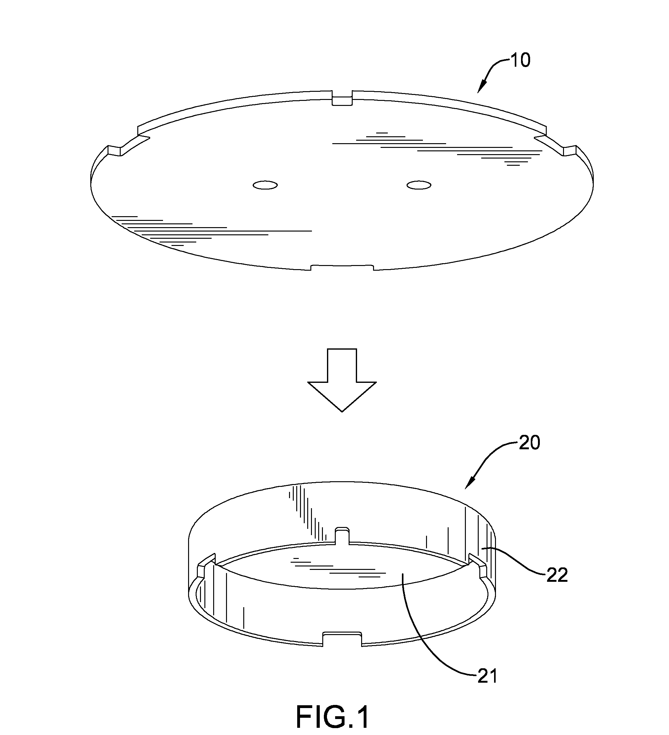
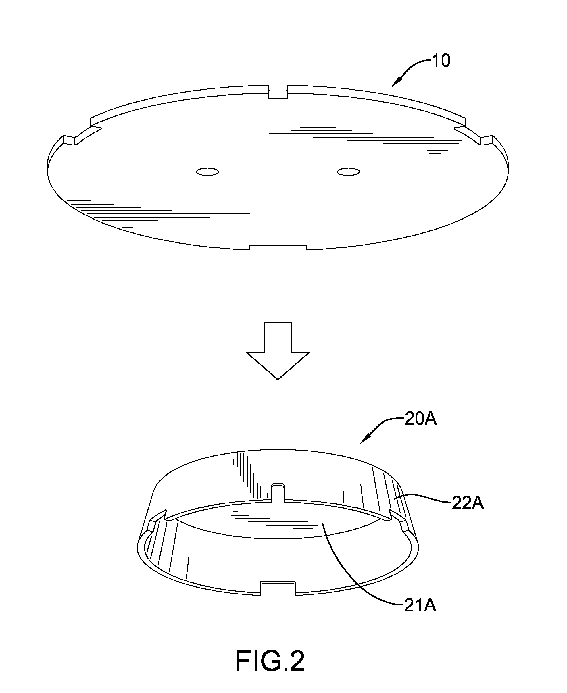
[0020]With reference to FIGS. 1 to 5, a heat conductive device for an LED formed by a manufacturing method in accordance with the present invention has a heat sink 30 and an LED carrier 20, 20A. The heat sink 30 has a cylindrical or conical engagement recess formed therein. The LED carrier 20, 20A engages the heat sink 30, is mounted in the heat sink 30, and has a mounting portion 21, 21A and a heat-conducting wall 22, 22A. The mounting portion 21, 21A is circular in shape. The heat-conducting wall 22, 22A is perpendicularly and conically formed along and protrudes from a perimeter of the mounting portion 21, 21A as respectively shown in FIGS. 1 and 2. An outer diameter of the heat-conducting wall 22, 22A is larger than a diameter of the mounting portion 21, 21A.

[0021]The manufacturing method has the following steps.

[0022]1) Manufacture the heat sink 30 by cold forge forming and form the engagement recess in the heat sink 30.

[0023]2) Place a heat-conducting disc 10 in a die and punc...


PUM

PropertyMeasurementUnit
Diameteraaaaaaaaaa
Electrical conductoraaaaaaaaaa

Abstract

A manufacturing method of heat conductive device for an LED has steps of forming a heat sink and an engagement recess in the heat sink by cold forge, punching a heat-conducting disc to form an LED carrier having a mounting portion and a heat-conducting wall formed around the mounting portion, soldering multiple LEDs on the LED carrier, and heating the heat sink to thermally expand the heat sink and assembling the LED carrier and the heat sink so that the heat-conducting wall is assembled with the engagement recess and further chilling the heat sink to thermally retract and tightly hold the LED carrier. The manufacturing method increases contact area and reduces air gaps between the LED carrier and the heat sink to effectively enhance the heat-conducting efficiency of the LED carrier so that the LEDs are operated at a suitable operating temperature to secure a prolonged life duration.

Description

BACKGROUND OF THE INVENTION[0001]1. Field of the Invention[0002]The present invention relates to a manufacturing method of a heat conductive device for a light-emitting diode (LED), and more particularly to a forming method of a heat conductive device capable of enhancing heat conduction efficiency for transferring heat generated by an LED.[0003]2. Description of the Related Art[0004]Currently an LED lamp has an LED carrier mounted therein, multiple light-emitting diodes mounted on the LED carrier and a heat sink adjacently connected to the LED carrier. The LED carrier has a heat-dissipating surface formed on a top surface of the LED carrier and contacting the heat sink through a thermal conductive adhesive. Heat generated by lighting the LED lamp can be transferred to a heat-dissipating surface of the heat sink through the LED carrier and the thermal conductive adhesive for the purpose of heat dissipation.[0005]As the foregoing LED carrier only employs the single heat-conducting su...

Claims


Application Information

Patent Timeline
IPC IPC(8): H05K13/04
CPCH01C1/084Y10T29/49144F21V19/005F21Y2101/02F21K9/30F21K9/90F21K9/1375H05K7/20F28F2275/127F21V29/70F21V29/713Y10T29/49865Y10T29/49002Y10T29/49826Y10T29/4913F21V19/004F21K9/20F21K9/23F21Y2115/10F21V29/00
Inventor LEE, TSU
Owner PAN JIT INT
Why Eureka
Try Eureka