
Waste gate valve device

a gate valve and gate valve technology, applied in the direction of combustion engines, engine controllers, machines/engines, etc., can solve the problems of difficult control of the inability to manage the responsiveness of the exhaust turbine, so as to reduce the area of the exhaust gas passag

Inactive Publication Date: 2012-12-13
MITSUBISHI HEAVY IND LTD
View PDF9 Cites 71 Cited by
  • Summary
  • Abstract
  • Description
  • Claims
  • Application Information

AI Technical Summary

Benefits of technology

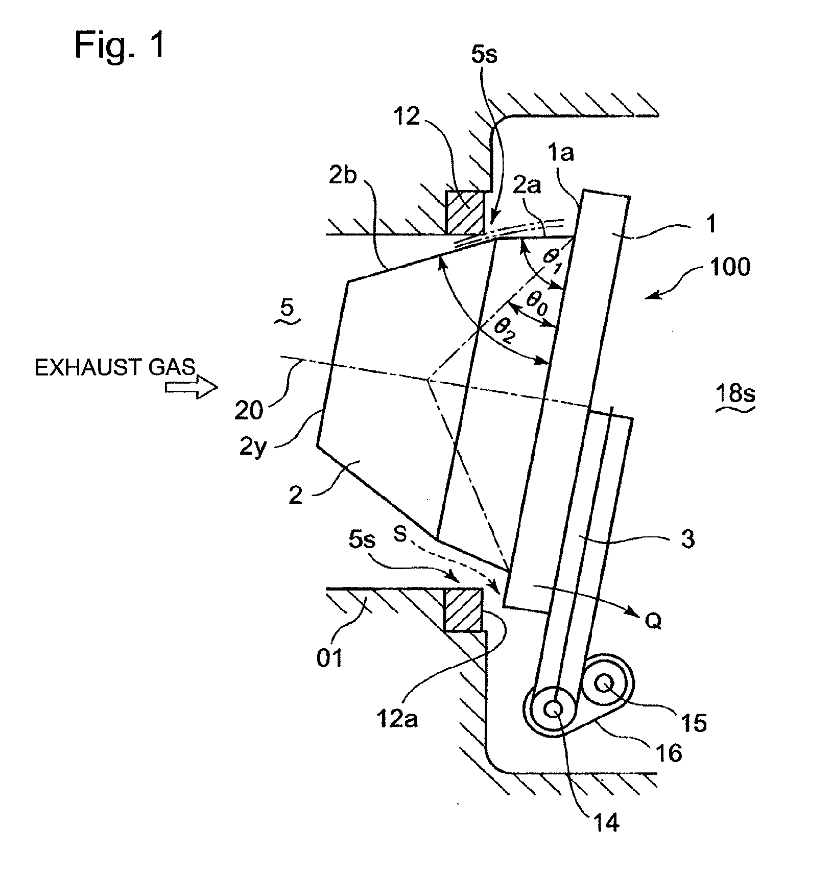
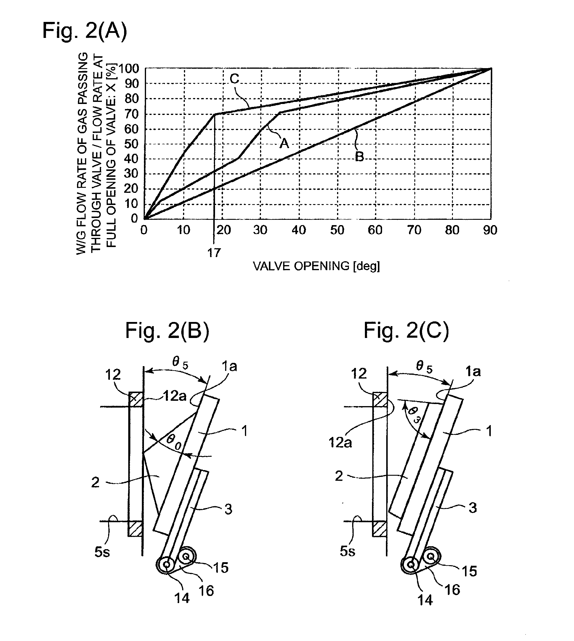
[0088]According to the present invention, in the waste gate valve provided with the valve body of a swing movement type, the valve body of the waste gate valve is provided with a protrusion of a prescribed height on a touching side of the valve body where the valve body touches the seat face, the protrusion being configured so as to reduce an exhaust gas passage area of the communication. Hence, the ratio X (%) of the flow rate of a gas passing by the valve body can be proportionally increased with respect to the valve opening, in the whole range of the valve opening from the range where the valve opening is extremely small (almost in an opening range of 0 to 20 degrees) to a range of greater valve opening.
[0089]Thus, the control of the responsiveness of the exhaust turbine can be smoothly performed in the whole range of the valve opening of the waste gate valve.

Problems solved by technology

And, in the flow rate characteristic of such a waste gate valve, it becomes difficult to control the responsiveness of the exhaust turbine; namely, the responsiveness of the exhaust turbine becomes unmanageable.

Method used


Image

  • Waste gate valve device
  • Waste gate valve device
  • Waste gate valve device

Examples


Embodiment Construction

[0123]Hereafter, the present invention will be described in detail with reference to the modes or embodiments shown in the figures. However, the dimensions, materials, shape, the relative placement and so on of a component described in these modes or embodiments shall not be construed as limiting the scope of the invention thereto, unless especially specific mention is made.

First Mode

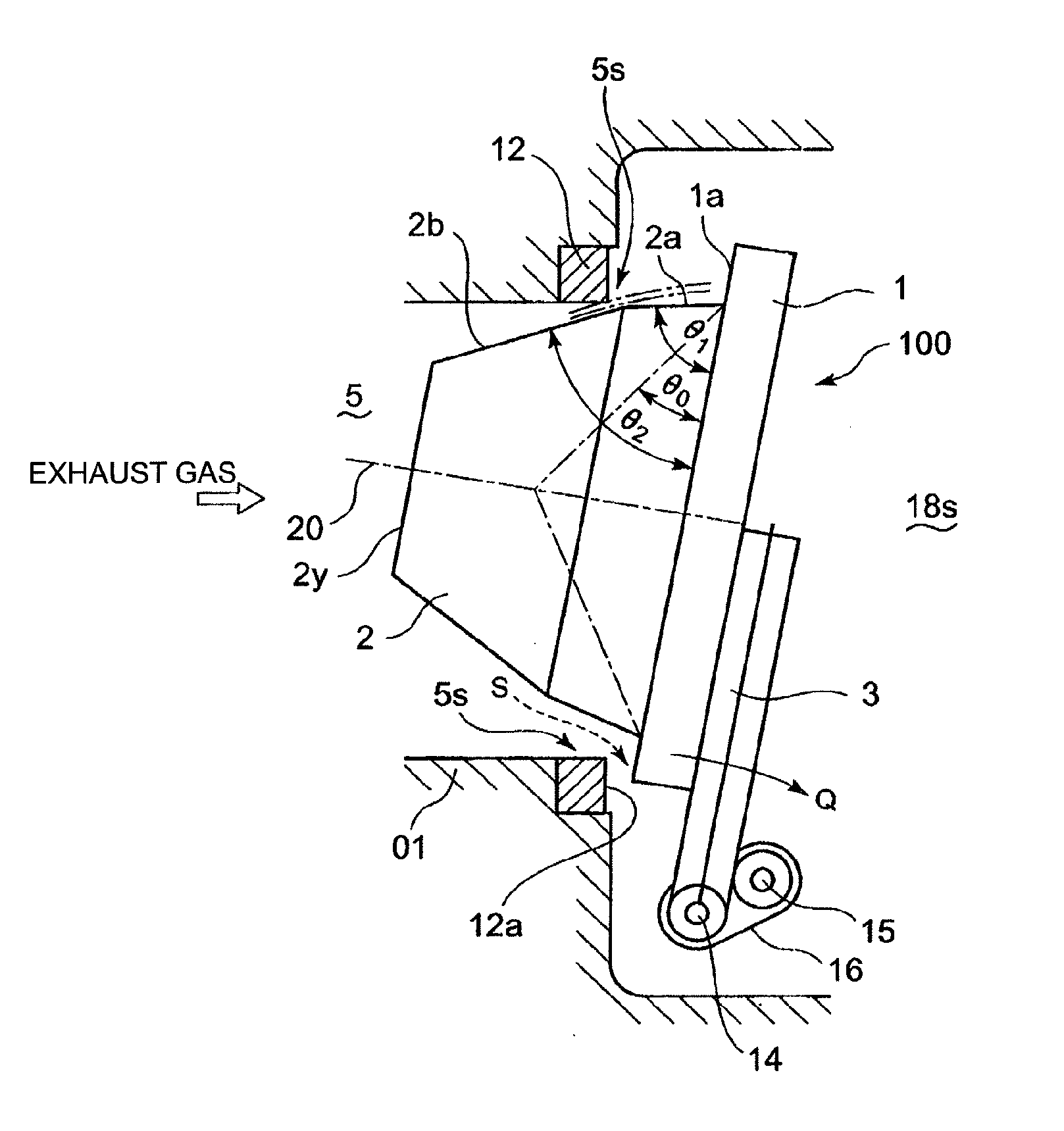
[0124]FIG. 1 shows a longitudinal cross section of a waste gate valve according to a first mode of the present invention. FIG. 2(A) shows a relationship between the valve opening and the ratio of the flow rate of a gas passing through the waste gate valve W / G to the gas flow rate at the full opening of the waste gate valve W / G, in the first mode. FIG. 2(B) as well as FIG. 2(C) shows an example of a longitudinal cross section of the waste gate valve according to a second mode of the present invention; namely, two examples are shown in FIGS. 2(B) and FIG. 2(C).

[0125]As shown in FIG. 18, in a waste gate va...


PUM


Abstract

A waste gate valve device in which a waste gate valve 100 is fully closed when a valve body of the waste gate valve 100 moves from an exhaust outlet passage 18s side toward an exhaust bypass passage 5 side and touches a seat face 12a of a valve seat part 12, wherein the valve body of the waste gate valve is provided with a protrusion 2 of a prescribed height on a touching side where the valve body of the waste gate valve touches the seat face 12a, the protrusion being configured so as to reduce an exhaust gas passage area of the exhaust gas.

Description

BACKGROUND OF THE INVENTION[0001]1. Field of the Invention[0002]The present invention relates to a waste gate valve device which opens and closes an exhaust bypass passage that bypasses an exhaust turbine driven by an exhaust gas from an engine and connects an exhaust passage toward the exhaust turbine to an exhaust gas outlet passage.[0003]2. Background of the Invention[0004]An exhaust turbocharger of a relatively small size is provided with a waste gate valve which opens and closes an exhaust bypass passage that bypasses an exhaust turbine driven by an exhaust gas and connects an exhaust passage toward the exhaust turbine to an exhaust gas outlet passage. When the flow rate of the exhaust gas from the engine is excessive, the waste gate valve is controlled so that: the waste valve is opened; and a part of the exhaust gas is let bypass the exhaust turbine and escape toward the exhaust gas outlet passage. And, the exhaust gas flow rate is maintained at an appropriate level. In perfo...

Claims


Application Information

Patent Timeline
IPC IPC(8): F02B37/18
CPCF01D17/105F02B37/183F05D2220/40Y02T10/144Y02T10/16F02B37/186Y02T10/12F02B37/18F02B37/12
Inventor YASOSHIMA, TAKESHI
Owner MITSUBISHI HEAVY IND LTD
Learn More