Heating and cooling systems and methods

a technology of heat exchange rate and cooling system, applied in the field of vapor compression system, can solve the problem of less than optimal exchange rate, and achieve the effect of overcoming technical barriers and recognizing system potential

Inactive Publication Date: 2012-12-13
ABARIDY
View PDF0 Cites 28 Cited by
  • Summary
  • Abstract
  • Description
  • Claims
  • Application Information

AI Technical Summary

Benefits of technology

[0006]Provided herein are cooling and heating systems that that are configured to provide heating and / or cooling at improved coefficient of performance (COP) in relation to other systems currently available. In some instances, cooling and / or heating system provided herein can operate without the use of a compressor. During operation, such systems can be quiet in relation to other systems currently available, thereby aiding in minimizing noise pollution in urban and industrial settings. The improved performance of systems provided herein aids in minimizing environmental pollution and helping offset or mitigate the effects of global warming.

Problems solved by technology

This exchange rate is less than optimal and may directly correlate with the rise in pressure times the volumetric flow rate.

Method used


Image

  • Heating and cooling systems and methods
  • Heating and cooling systems and methods
  • Heating and cooling systems and methods

Examples


example

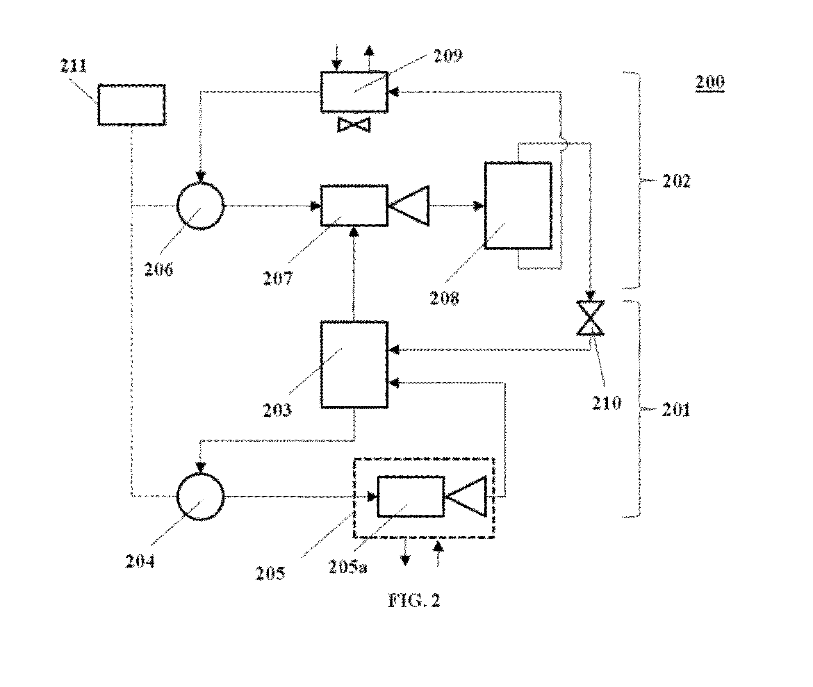
[0152]A cooling system, such as the system of FIG. 2 adapted for cooling applications, is used for cooling applications. The cooling system includes a pump, ejector device and reservoir. Two use cases are conducted. In a first case, the reservoir includes pure acetone (bottom plot). In a second case, the reservoir includes a mixture of 30% acetone and 70% water (top plot). The temperature of the reservoir (y-axis) as a function of time (x-axis) in each of the two use cases is shown in FIG. 11. During use, for the acetone-water mixture the temperature of the reservoir decreases from about 40° C. to about 5° C. in about 6 minutes. For pure acetone, the temperature of the reservoir decreases from about 40° C. to about −19° C. in about 6 minutes. The system is able to achieve a cooling rate of about 2.1 kilowatts (kW). The input power to the pump is approximately 35 watts (W) in both use cases.

[0153]Although systems and methods provided herein have been described in the context of cooli...


PUM


Abstract

A fluid flow system comprises a first pump and an ejector downstream of the pump. The first pump facilitates the flow of a driver fluid through the ejector. In the ejector, the driver fluid mixes with a suction fluid. The ejector is operatively coupled to a fluid reservoir, which in some cases is associated with a cycle having a second pump and an evaporator. The fluid reservoir includes the suction fluid. A heat exchanger downstream of the ejector removes heat from the driver fluid, and from the heat exchanger the driver fluid is directed to the first pump. The fluid flow system can include a fluid separator downstream of the ejector for separating the driver fluid from the suction fluid.

Description

CROSS-REFERENCE[0001]This application claims the benefit of U.S. Provisional Application No. 61 / 433,165 filed Jan. 14, 2011, and U.S. Provisional Application No. 61 / 443,705, filed Feb. 16, 2011, which applications are entirely incorporated herein by reference.BACKGROUND OF THE INVENTION[0002]A vapor compression system typically includes a compressor, a condenser, and an evaporator, and in some cases an expansion device. In a vapor compression system, a refrigerant gas is compressed, whereby the temperature of the gas is increased beyond that of the ambient temperature. The compressed gas then flows through a condenser and turned into a liquid. The condensed and liquefied gas then flows through an expansion device, which drops the pressure and the corresponding temperature of the fluid. The refrigerant is then boiled in an evaporator.[0003]FIG. 1 illustrates a vapor compression system 100, as may be found in some current vapor compression systems, such as those used in a home or auto...

Claims


Application Information

Patent Timeline
Patent Type & Authority Applications(United States)
IPC IPC(8): F16L53/00
CPCF25B2341/0015F25B41/00Y10T137/0318Y10T137/6416
Inventor GIELDA, THOMAS P.HARMAN, JAYDEN D.FARSAD, KASRA
Owner ABARIDY
Why Eureka
Try Eureka