Eureka AIR delivers breakthrough ideas for toughest innovation challenges, trusted by R&D personnel around the world.

Method and magnetic resonance system for distortion correction in magnetic resonance imaging

a magnetic resonance imaging and distortion correction technology, applied can solve the problems of high sensitivity to bsub>0 /sub>field distortion or induced susceptibilities, and achieve the effect of improving the distortion correction in the field of magnetic resonance imaging

Active Publication Date: 2012-12-13
SIEMENS HEALTHCARE GMBH
View PDF6 Cites 25 Cited by
  • Summary
  • Abstract
  • Description
  • Claims
  • Application Information

AI Technical Summary

Benefits of technology

[0013]An object of the present invention is to improve a distortion correction in magnetic resonance imaging, particularly in the case of a spiral-shaped or radial scanning.
[0017]Even in non-Cartesian echoplanar imaging (such as spiral echoplanar imaging or radial MR imaging, for example), it is possible to determine and correct a geometric distortion of the image points, similar to as in Cartesian echoplanar imaging.
[0022]In a further method according to the present invention, distortion correction is provided in magnetic resonance echoplanar imaging. In the method an examination subject is excited with a single radio-frequency excitation for an acquisition of at least one first MR data set and one second MR data set. Expressed differently, only one radio-frequency excitation is applied for slice selection, for example, and the first and second MR data set are thereupon acquired as described in the following. No additional radio-frequency excitation is implemented between the acquisition of the first MR data set and the acquisition of the second MR data set. The first MR data set is acquired in a raw data space in that the raw data space is scanned—beginning with a first point of said raw data space—along a predefined trajectory by means of a modulation of a readout gradient and a phase coding gradient. Furthermore, the second MR data set is acquired in a raw data space in that the raw data space is scanned—beginning with a second point of said raw data space—along a predefined trajectory. The second point is different than the first point. A first complex MR image that includes first phase information for image points of the first MR image is determined depending on the first MR data set. A second complex MR image is determined depending on the second MR data set. The second complex MR image includes second phase information for image points of the second MR image. Depending on the first and second phase information, a geometric deformation for image points of the first or second MR image is determined (for example in the form of a field map or displacement map) on the basis of the PLACE method. The first MR data set and the second MR data set are thus acquired with the use of a multi-echo sequence within an MR excitation, instead of with two individual echo sequences with two different MR excitations as are used in the PLACE method. The first MR data set and the second MR data set can be acquired at an interval of a few milliseconds (for example at an interval of 50 to 100 ms) so that only slight differences can occur in the first and second MR data set due to movements of the examination subject or temporal BO field changes, so a reliable correction of the distortion is possible with the use of the phase information.
[0023]According to one embodiment, the previously described echoplanar imaging with a single radio-frequency excitation for the first MR data set and the second MR data set can comprise a multi-spin echo sequence in which a first radio-frequency refocusing pulse is applied before the acquisition of the first MR data set and a second radio-frequency refocusing pulse is applied between the acquisition of the first MR data set and the acquisition of the second MR data set. The first refocusing pulse can also include a magnetic preparation, for example an adjustment of diffusion weighting gradients. The diffusion weighting gradient can be adjusted in an arbitrary direction, for example in a readout direction or in a phase coding direction. The individual excitation for the acquisition of the first and second MR data set is particularly advantageous when the time period for the difference preparation primarily influences the duration of the acquisition sequence. With the (thus shortened) echoplanar imaging, the use of multiple refocused echoes within the T2 relaxation time is possible. To further accelerate the echoplanar imaging method, the method can be combined with methods for parallel imaging (Parallel Acquisition Technique PAT or Parallel Imaging PI) or what is known as “Zoomed Echoplanar Imaging” with reduced field of view, or a segmented echoplanar imaging with a segmented readout or phase direction.

Problems solved by technology

A problem with such fast imaging methods, however, is their high sensitivity to B0 field distortions or induced susceptibilities, since the readout time per excitation is significantly longer compared to other methods that acquire only portions of a line or one line in raw data space.

Method used


Image

  • Method and magnetic resonance system for distortion correction in magnetic resonance imaging
  • Method and magnetic resonance system for distortion correction in magnetic resonance imaging
  • Method and magnetic resonance system for distortion correction in magnetic resonance imaging

Examples


Embodiment Construction

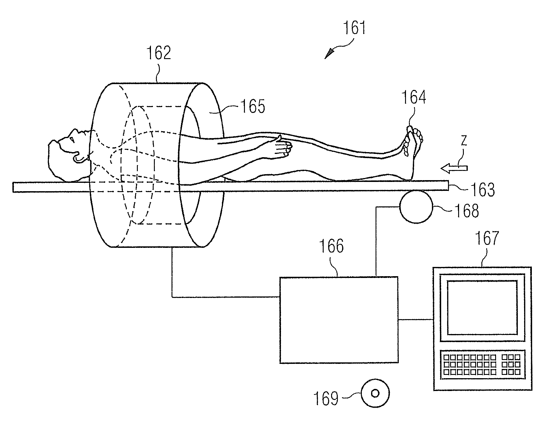
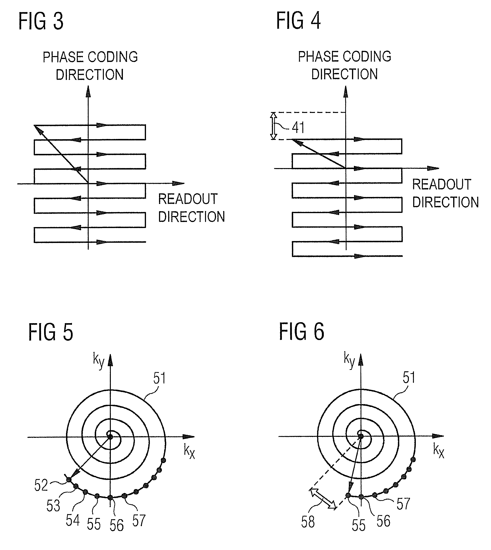
[0043]FIG. 5 shows a trajectory 51 in an X / Y plane of the raw data space (what is known as k-space). The trajectory 51 travels in the shape of as spiral from the outside in and ends at the middle point of the raw data space. Data are acquired along the trajectory 51 to fill the raw data space at points 52-57. Additional sample points are present on the trajectory but are not provided with additional reference characters for clarity. Moreover, additional sample points are present along the trajectory 51 but are likewise not drawn in FIG. 5 for clarity. The additional sample points proceed along the trajectory 51 up to the middle point of the spiral-shaped trajectory 51.

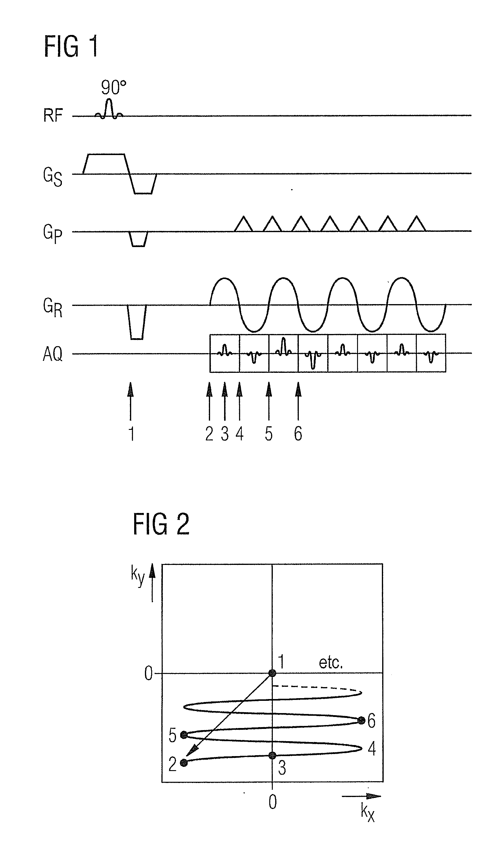
[0044]FIG. 7 shows a sequence diagram of the gradients Gx and Gy in order to scan the raw data space in a spiral shape as shown in FIG. 5. For this purpose, a single slice of the raw data space is initially selected and excited with a radio-frequency pulse. This excitation is not shown in detail in FIG. 7, but rather i...


PUM


Abstract

In a method for distortion correction in spiral magnetic resonance imaging, a first MR data set is acquired by scanning raw data space along a spiral trajectory beginning at a first point. A first complex MR image is determined from the first MR data set, which includes first phase information for image points of the first MR image. A second MR data set is acquired by scanning raw data space along the spiral trajectory beginning at a second point that differs from the first point. A second complex MR image is determined from the second MR data set, which includes second phase information for image points of the second MR image. A geometric distortion for image points of the first or second MR image is determined from the first and second phase information, for example with a PLACE method.

Description

BACKGROUND OF THE INVENTION[0001]1. Field of the Invention[0002]The present invention concerns methods for magnetic resonance imaging that can be used in medical engineering to examine patients. The present invention in particular concerns methods to correct distortions or deformations in the phase coding direction that can occur given a use of echoplanar sequences (known as EPI sequences) and that can negatively affect image quality.[0003]The present invention likewise concerns a magnetic resonance system for implementing such methods.[0004]2. Description of the Prior Art[0005]Magnetic resonance tomography (MRT), which is used for magnetic resonance imaging, is based on the physical principle of nuclear magnetic resonance. In magnetic resonance tomography, an examination subject (a patient, for example) is exposed to a constant, strong magnetic field. The nuclear spins of the atoms in the subject, which were previously oriented at random, thereby align. Radio-frequency waves can ex...

Claims


Application Information

Patent Timeline
IPC IPC(8): G06K9/40G01R33/34G01R33/565
CPCA61B5/055G01R33/4824G01R33/56572G01R33/56554G01R33/5616
Inventor PFEUFFER, JOSEF
Owner SIEMENS HEALTHCARE GMBH
Why Eureka
Eureka Blog
Learn More