Imaging apparatus, imaging method, program, and integrated circuit

a technology of imaging apparatus and integrated circuit, which is applied in the field of imaging apparatus, can solve the problems of difficult differentiation between psfs, and achieve the effect of stable and highly accurate determination of object distan

Inactive Publication Date: 2012-12-13
PANASONIC CORP
View PDF3 Cites 6 Cited by
  • Summary
  • Abstract
  • Description
  • Claims
  • Application Information

AI Technical Summary

Benefits of technology

[0025]The imaging apparatus according to the present invention calculates a form of a PSF included in an image by using at least two

Problems solved by technology

Therefore, the DFD has a problem in that it is ambiguous whether a PSF is one that is behind the image point or one that is in front o

Method used


Image

  • Imaging apparatus, imaging method, program, and integrated circuit
  • Imaging apparatus, imaging method, program, and integrated circuit
  • Imaging apparatus, imaging method, program, and integrated circuit

Examples


embodiment 1

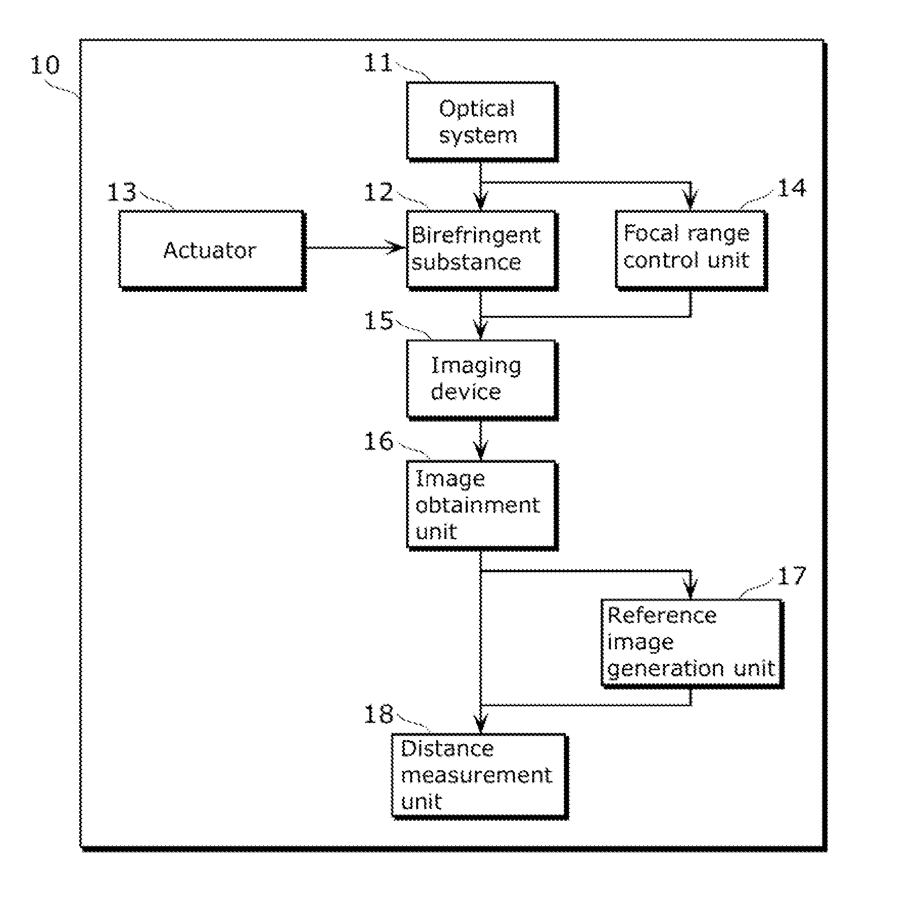
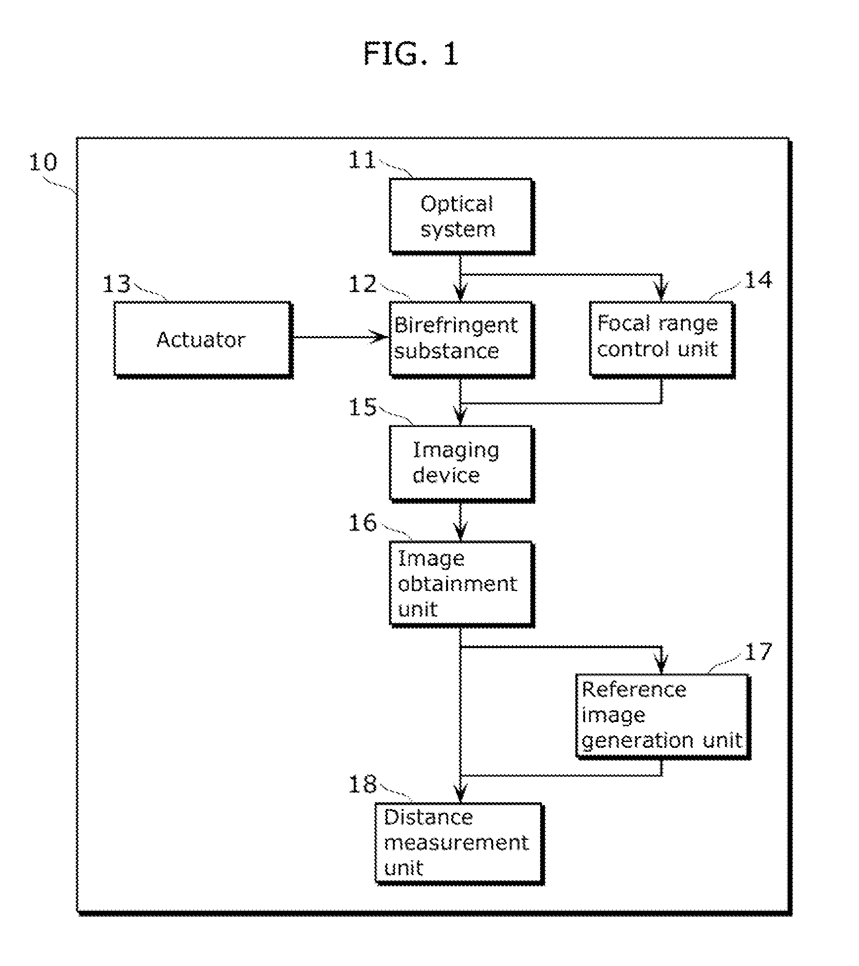
[0038]FIG. 1 is a block diagram showing a configuration of an imaging apparatus according to Embodiment 1 of the present invention.

[0039]An imaging apparatus 10 includes: an optical system 11, a birefringent substance 12, an actuator 13, a focal range control unit 14, an imaging device 15, an image obtainment unit 16, a reference image generation unit 17, and a distance measurement unit 18.

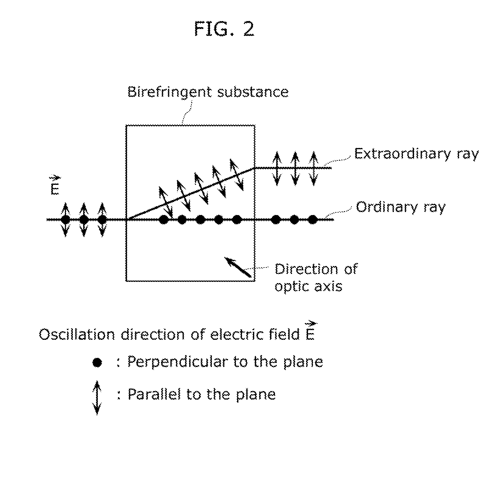
[0040]In FIG. 1, the optical system 11 forms an image of an object on the imaging device 15. The birefringent substance 12 which is an optical element having a birefringence effect is placed on the optical path between the imaging device 15 and the optical system 11. Of the light beams which have passed through the birefringent substance 12, the form of the PSF of especially an extraordinary ray is changed. The form of the PSF is changed between positions in front of and behind the image point corresponding to the object distance. The actuator 13 inserts or retracts the birefringent substance 12 w...

embodiment 2

[0074]An imaging apparatus 19 according to Embodiment 2 of the present invention has a configuration of splitting the ordinary ray and the extraordinary ray, and obtaining an image including only the ordinary ray and an image including only the extraordinary ray. FIG. 10 is a block diagram showing the configuration of the imaging apparatus 19 according to Embodiment 2 of the present invention. In FIG. 10, the same reference numbers are used for the elements same as in the imaging apparatus 10 in FIG. 1, and some of the descriptions of the elements are omitted. The imaging apparatus 19 includes: the optical system 11, a light beam splitting unit 20, the birefringent substance 12, the focal range control unit 14, an imaging device A21, an imaging device B22, an image obtainment unit A23, an image obtainment unit B24, the reference image generation unit 17, and the distance measurement unit 18.

[0075]In FIG. 10, the optical system 11 forms an image of an object on each of the imaging de...


PUM


Abstract

Ambiguous distinction of PSFs between positions in front of and behind an imaging point corresponding to a distance to an object is eliminated without decreasing the amount of light to be exposed, and the distance to the object is estimated from a small number of captured images. An imaging apparatus includes: an imaging device which captures an image; an optical system for forming an image of an object on the imaging device; a birefringent substance having a birefringence effect; and a distance measurement unit which measures a distance from the imaging device to the object, using the captured image and a point spread function having a form changed by the optical element between positions in front of and behind an image point corresponding to the distance to the object.

Description

TECHNICAL FIELD[0001]The present invention relates to an imaging apparatus for measuring a depth of a scene using a plurality of images captured from a single viewpoint.BACKGROUND ART[0002]Conventionally, various methods have been suggested for measuring, without contact, a depth of a three-dimensional scene, that is, a distance from the imaging apparatus to each object (hereinafter, referred to as an “object distance”). Such methods can be largely classified into an active technique and a passive technique. The active technique is to irradiate the object with infrared rays, ultrasound, or laser, and calculate the object distance based on a length of time until a wave which is reflected returns or an angle of the reflected wave. The passive technique is to calculate the object distance based on an image of the object. In particular, in the case of using an imaging apparatus such as a camera to measure the object distance, the passive technique which does not require an apparatus for...

Claims


Application Information

Patent Timeline
IPC IPC(8): H04N7/18
CPCG01B11/026G02B7/365G01C3/08
Inventor YASUGI, SHUNSUKE
Owner PANASONIC CORP
Why Eureka
Try Eureka