
Cof, cof carrier tape and drive circuit of liquid crystal television

a technology of drive circuit and carrier tape, which is applied in the direction of electrical apparatus construction details, instruments, and semiconductor/solid-state device details, can solve the problems of massive waste of materials in the production process, and achieve the effects of saving cof area, reducing production costs, and improving the utilization ratio of carrier tap

Inactive Publication Date: 2012-12-13
SHENZHEN CHINA STAR OPTOELECTRONICS TECH CO LTD
View PDF5 Cites 0 Cited by
  • Summary
  • Abstract
  • Description
  • Claims
  • Application Information

AI Technical Summary

Benefits of technology

[0004]The main purpose of the disclosure is to provide a COF, a COF carrier tape and a drive circuit of the liquid crystal display television, which aims at saving COF area, improving the utilization ratio of the carrier tape and effectively lowering the production cost.
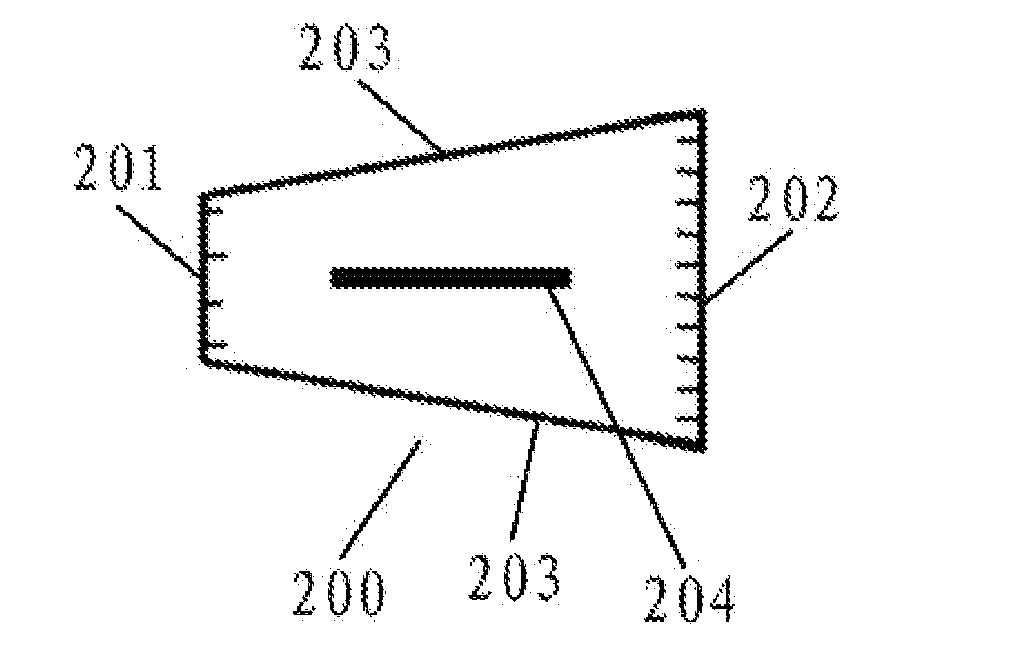
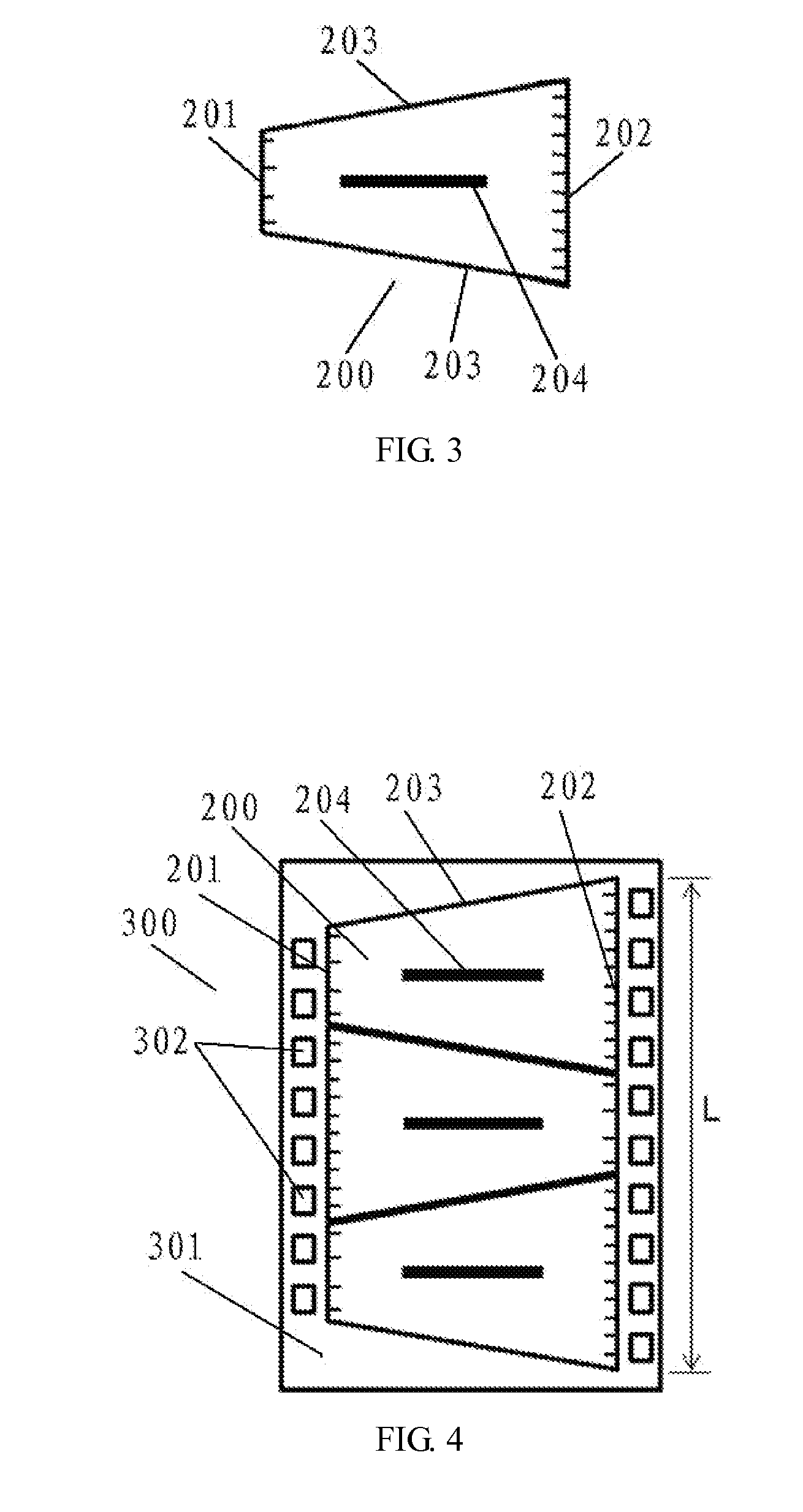
[0018]The COF of the disclosure is a quadrilateral structure with two wiring edges mutually paralleled, meanwhile, the lengths of the two wiring edges are different; for examples, the COF is a trapezoid, a right trapezoid or an isosceles trapezoid. Such shaped COF can be suitable for the ones with sparse wiring quantity on one wiring edge and with dense wiring quantity on the other wiring edge. The trapezoid-structured COF saves more materials and reduces more costs compared with the rectangle-structured COF. COF carrier tape includes a COF tape formed by orderly connecting several COFs and a carrier connected with said COF tape. The appearance of said COF is a trapezoid consisting of two paralleled wiring edges and two unparalleled side edges. The longer wiring edge of one COF and the shorter wiring edge of the other COF between two adjacent COFs are connected and lie in a same straight line, the shorter wiring edges and the longer wiring edges of the other two COFs also lie in a same straight line. Specifically, the adjacent COFs are arranged on the COF carrier tape by rotating relatively 180-degree, the same-shaped COF can be obtained by punching from the COF carrier tape. Therefore, in the carrier-tape type semiconductor device with the COF of the disclosure is able to increase the quantity of COF on the carrier tape of specific length, so that the cost can be lowered to a large extent.

Problems solved by technology

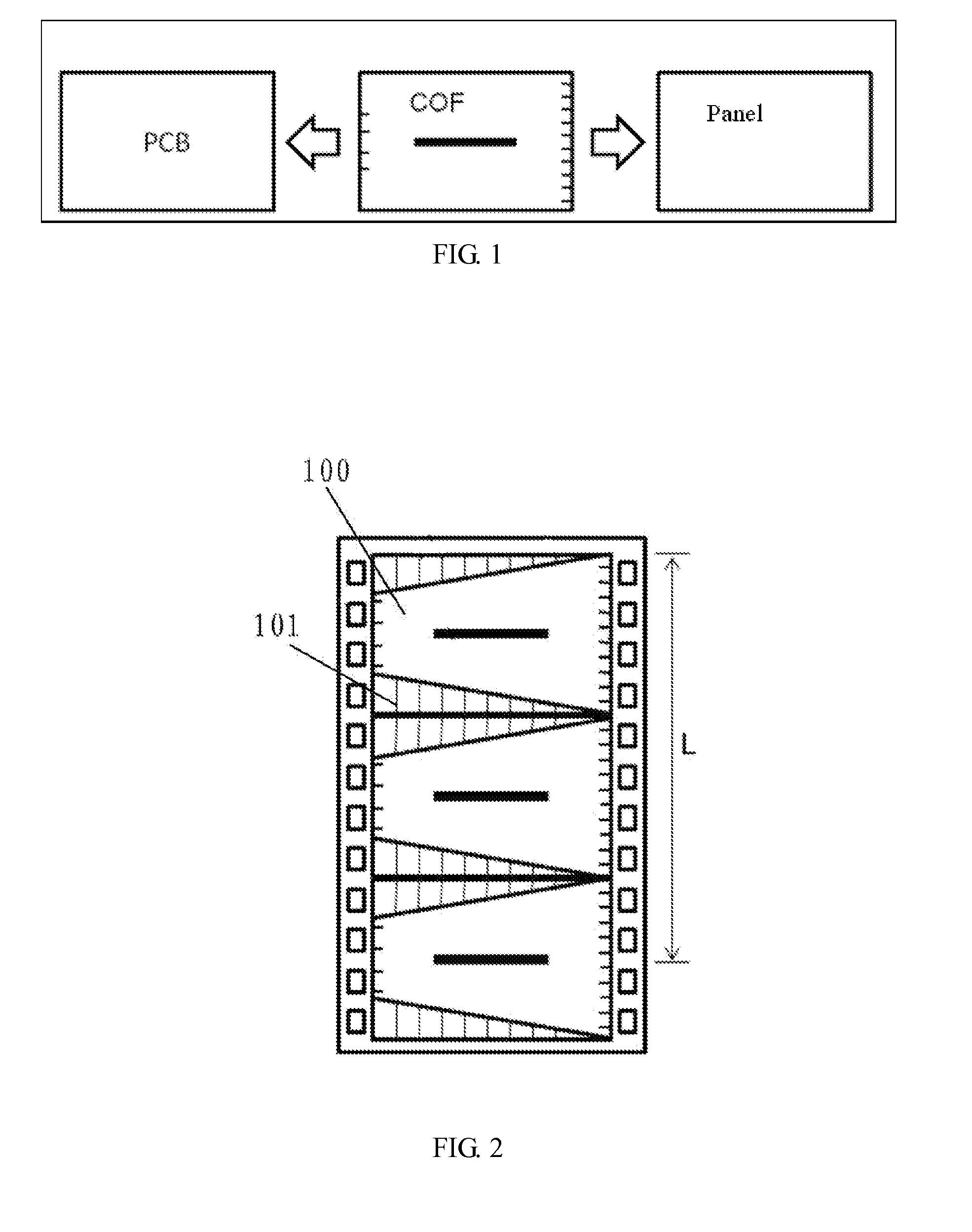
The COF 100 in the COF carrier tape is a rectangular structure; the area of shadow part 101 is useless, however, it still occupies partial area of the carrier tape and will waste massive material in the process of production.

Method used


Image

  • Cof, cof carrier tape and drive circuit of liquid crystal television
  • Cof, cof carrier tape and drive circuit of liquid crystal television
  • Cof, cof carrier tape and drive circuit of liquid crystal television

Examples


Embodiment Construction

[0026]It should be understood that the described exemplary embodiment is only used for illustrating this disclosure rather than limiting.

[0027]Take FIG. 3 as a reference, which is the schematic diagram showing the structure of the COF 200 in a first embodiment according to the disclosure. The appearance of COF 200 is shaped as a trapezoid formed with two opposite paralleled wiring edges and two unparalleled side edges 203 connected therebetween. The COF 200 in this embodiment is an isosceles trapezoid structure, the two wiring edges of which respectively refer to the upper bottom side 201 and the lower bottom side 202 of the trapezoid. One short wiring edge (upper bottom side 201) of the COF 200 is provided with a plurality of connecting wires capable of being connected with the external PCB, and the other long wiring edge (lower bottom side 202) is provided with a plurality of connecting wires capable of being connected with the external panel. The wirings arranged on the upper bot...


PUM


Abstract

A COF tape is formed by orderly connecting several COFs and a carrier connected with said COF tape. The appearance of said COF is a trapezoid consisting of two paralleled wiring edges and two unparalleled side edges. The longer wiring edge of one COF and the shorter wiring edge of the other COF between the two adjacent COFs are connected and lie in a same straight line; the shorter wiring edges and the longer wiring edges of the other two COFs also lie in a same straight line. The disclosure also discloses a COF and a drive circuit for liquid crystal display television. The COF of the disclosure saves materials; the carrier-tape type semiconductor device with the COF of the disclosure is able to increase the quantity of COF on the carrier tape of specific length, so that the cost can be lowered to a large extent.

Description

BACKGROUND[0001]1. Technical Field[0002]The disclosure relates to a COF (Chip On Film), specifically to a COF, COF carrier tape and a drive circuit of liquid crystal television.[0003]2. Description of Related Art COF carrier tape joints the semiconductor elements and then installs them on the long carrier tape. COF uses a soft additional circuit board as the packaged chip carrier in order to joint the chip and the soft substrate circuits; or COF only refers to the soft additional circuit board of the unpackaged chip. As is shown in FIG. 1, COF is formed by jointing the chip (such as source driver IC or gate driver IC, etc. see the black-coloured shadow part in FIG. 1) and installing the chip on a flexible wiring substrate on which the wiring diagrams are formed. The wiring diagrams of COF are generally composed of an internal lead connected with the chip electrode and an external lead connected with the external circuit. Generally, in the driver circuit of the liquid crystal display...

Claims


Application Information

Patent Timeline
IPC IPC(8): G02F1/1345H05K7/00
CPCH01L2924/0002G02F1/13452H05K1/189H05K2201/09027H01L23/4985H01L2924/00
Inventor LIN, PO-SHENLIAO, LIANG-CHANZHANG, YONG
Owner SHENZHEN CHINA STAR OPTOELECTRONICS TECH CO LTD
Learn More