Light Source Fixing Device, Light Source Assembly and Assembling Method Thereof
a technology for fixing devices and light sources, applied in the field of display, can solve the problems of significantly degrading the heat dissipation efficiency, and reducing the contact area, so as to simplify the assembling process, reduce the number of components to be assembled, and improve the reliability of the product.
- Summary
- Abstract
- Description
- Claims
- Application Information
AI Technical Summary
Benefits of technology
Problems solved by technology
Method used
Image
Examples
first embodiment
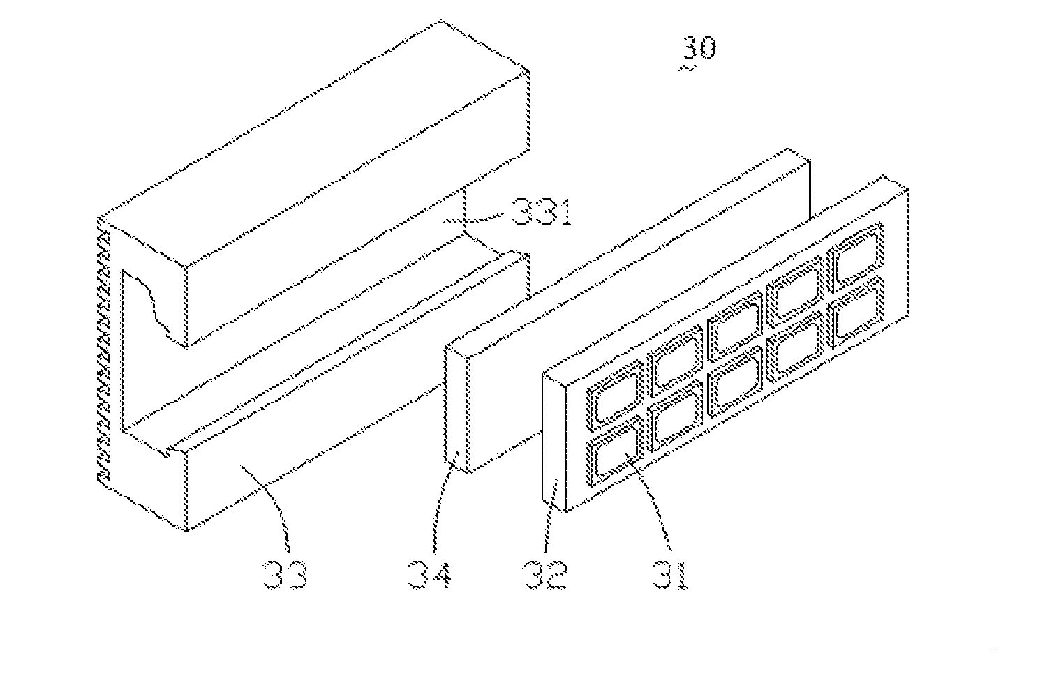
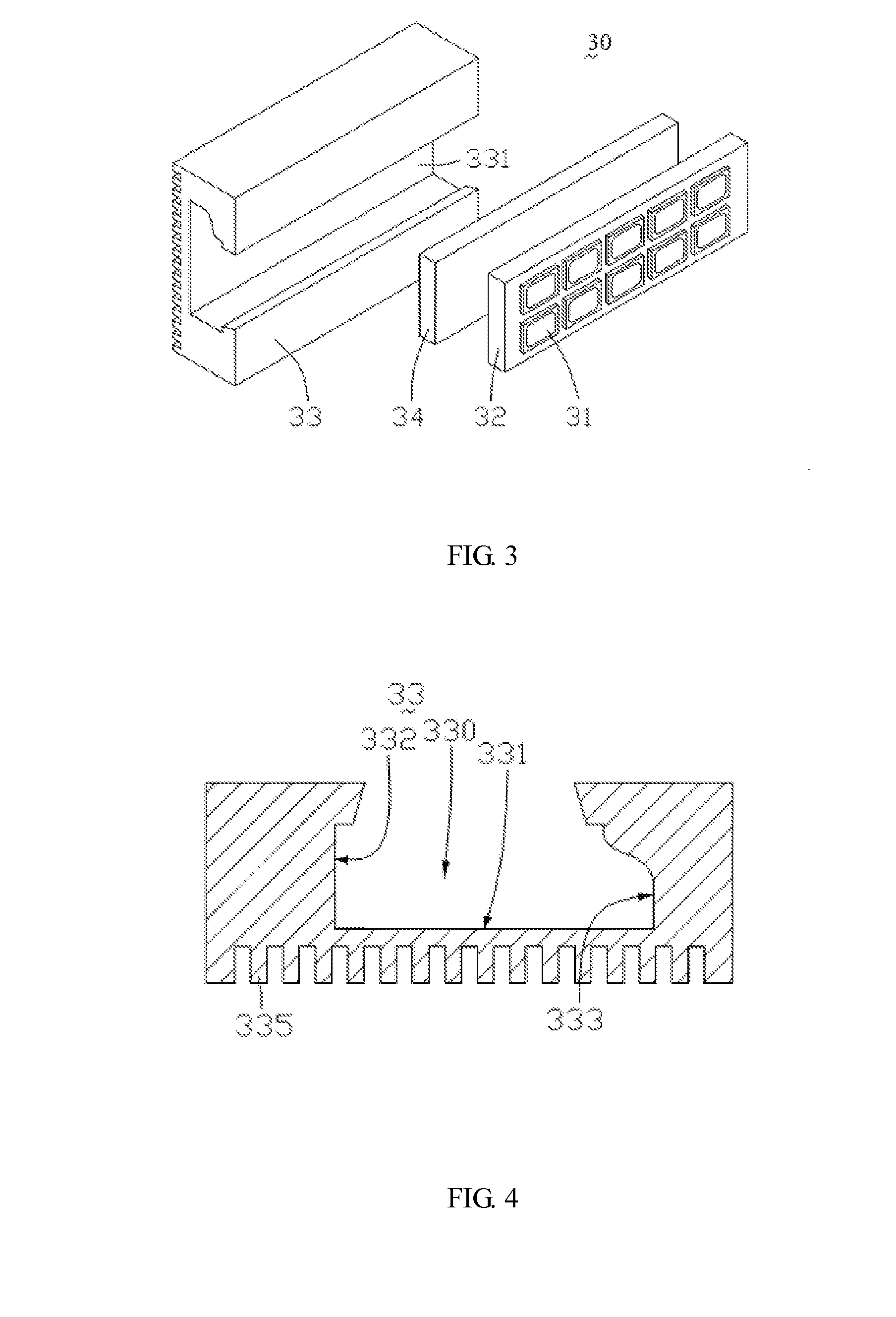
[0037]Referring to FIG. 3, a light source assembly 30 according to the present invention comprises a plurality of LEDs 31, a circuit board 32, a heat dissipating support 33 and an elastic element 34. The LEDs 31 and the circuit board 32 are collectively called a light emitting element.
[0038]The LEDs 31 are arranged in an array on a side surface of the circuit board 32. Each of the LEDs 31 is a point light source electrically connected to the circuit board 32. The circuit board 32 is a rigid printed circuit board (PCB) or a flexible PCB having a plurality of pads (not shown) and a printed circuit (not shown) disposed on a surface thereof. The pads are arranged in an array. Each of the pads corresponds to one of the LEDs 31; i.e., the LED 31 is welded onto the pad of the circuit board 32, correspondingly. The printed circuit on the surface of the circuit board 32 transmits an electric signal to the LED 31 via the pad to drive the LED 31. When the LEDs 31 arranged in an array operate, ...
second embodiment
[0045]FIG. 5 is a cross-sectional view of a light source assembly 30′ according to the present invention. Similar to the light source assembly 30 of FIG. 3, the light source assembly 30′ also comprises LEDs 31′, a circuit board 32′, a heat dissipating support 33′ and an elastic element 34′. The difference lies in that, in this embodiment, the LEDs 31′ are arranged in one row and the heat dissipating support 33′ is not formed with heat dissipating fins on a bottom thereof.
[0046]The present invention further provides an assembling method of a light source assembly, which mainly comprises a placing step and a pressing step. In the placing step, a supporting plate of a light emitting element is placed into a receiving recess of a heat dissipating support via an opening of the receiving recess. In the pressing step, the supporting plate is used to press an elastic element in the receiving recess to cause elastic deformation of the elastic element and to have the supporting plate of the l...
third embodiment
[0050]Referring to FIG. 7 and FIG. 8 together, FIG. 7 is a schematic perspective view of a structure of a light source assembly according to the present invention, and FIG. 8 is a schematic view showing an assembling process flow of the light source assembly of FIG. 7.
[0051]The light source assembly 40 is substantially the same as the light source assembly 30 in the first embodiment 30 except that: a plurality of grooves 431 is further formed at the opening of the receiving recess 430 of the light source assembly 40, a plurality of protrusions 421 is formed correspondingly at two sides of the circuit board 42, and the protrusions 421 have a profile matching with a profile of the grooves 431. When the light source assembly 40 is assembled, a light emitting element with the protrusions 421 at sides thereof is firstly placed into the opening of the receiving recess 430 in such a way that the protrusions 421 are disposed into the grooves 431; then the elastic element 44 in the receiving...
PUM
| Property | Measurement | Unit |
|---|---|---|
| distance | aaaaa | aaaaa |
| width | aaaaa | aaaaa |
| thermally conductive | aaaaa | aaaaa |
Abstract
Description
Claims
Application Information
 - R&D
- Intellectual Property
- Life Sciences
- Materials
- Tech Scout
- Unparalleled Data Quality
- Higher Quality Content
- 60% Fewer Hallucinations
Browse by: Latest US Patents, China's latest patents, Technical Efficacy Thesaurus, Application Domain, Technology Topic, Popular Technical Reports.
© 2025 PatSnap. All rights reserved.Legal|Privacy policy|Modern Slavery Act Transparency Statement|Sitemap|About US| Contact US: help@patsnap.com


