Solar Module and Method for its Operation

a solar module and solar energy technology, applied in photovoltaics, electric variable regulation, ac-dc conversion, etc., can solve the problems of inability to operate, inability to operate, and inability to meet the requirements of the inverter, so as to achieve the effect of economical manufacture and efficient operation

Active Publication Date: 2012-12-13
SEMIKRON ELECTRONICS GMBH & CO KG
View PDF6 Cites 4 Cited by
  • Summary
  • Abstract
  • Description
  • Claims
  • Application Information

AI Technical Summary

Benefits of technology

[0012]The object of the invention is to provide an improved solar module which may more efficiently operate under all circumstances, and which is more economical to manufacture than heretofore known.

Problems solved by technology

The converter is therefore initially inoperative.
In the starting case outlined above, however, the permissible operating voltage of the inverter is exceeded considerably by the no-load voltage of the solar cell of 900 V. Direct starting is therefore not permissible under these circumstances because of the maximum operating voltage of the solar cell being exceeded by the no-load voltage of the solar cell.
However, since the transition operation lasts only a few seconds as compared with many hours of normal operation, during normal operation the converter then operates considerably below its design limits for nearly all of its operation.
This over-dimensioning of the circuitry adds considerably to its manufacturing cost.

Method used


Image

  • Solar Module and Method for its Operation
  • Solar Module and Method for its Operation
  • Solar Module and Method for its Operation

Examples


Embodiment Construction

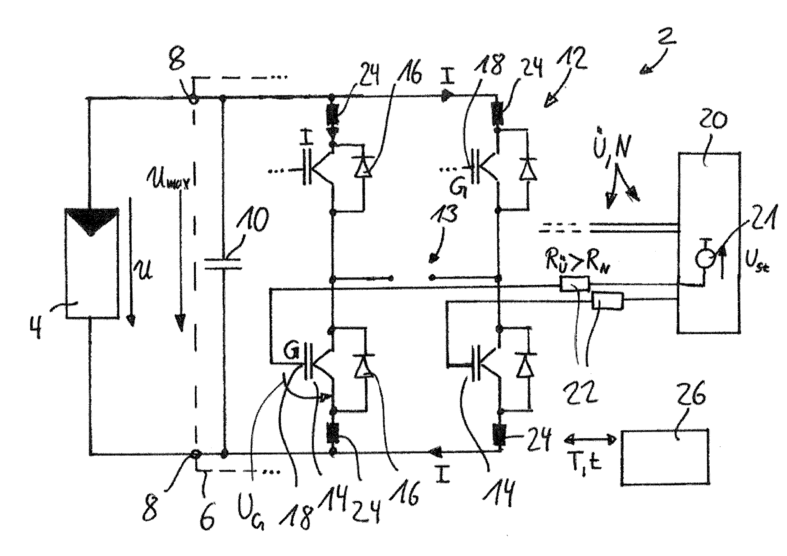
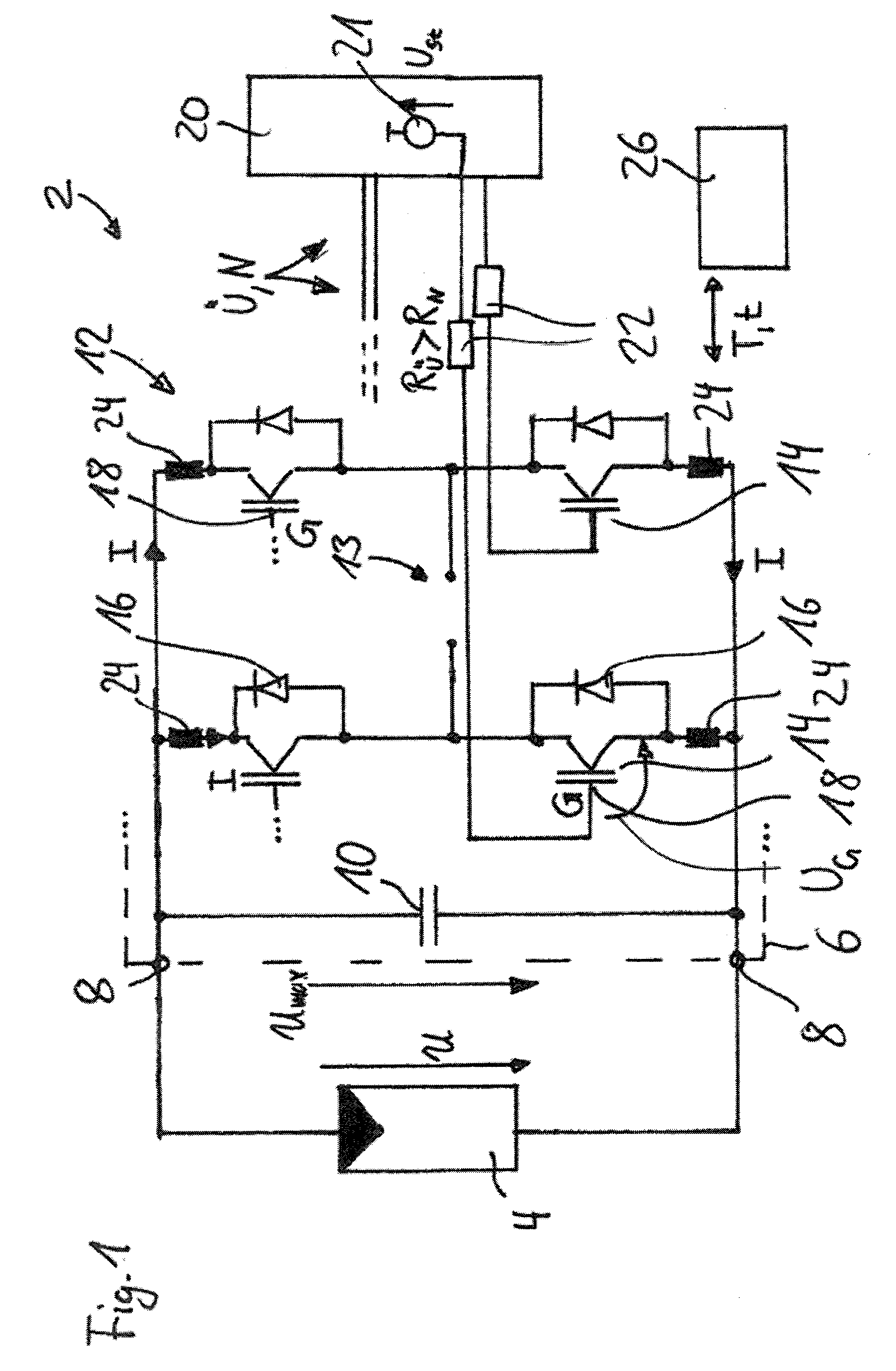
[0041]FIG. 1 shows, generally at 2 a solar module in accordance with the invention. Solar module 2 comprises a solar cell 4 and a converter 6. During operation, solar cell 4 generates a DC voltage U, which it feeds into an input 8 of converter 6. Converter 6 converts the DC voltage U into a voltage not specifically designated, for example a network voltage.

[0042]Converter 6 contains an intermediate circuit capacitor 10 and an H-bridge 12 having four semiconductor switches 14, preferably, as illustrated, in the form of IGBTs, with which respective diodes 16 are connected in anti-parallel. Each semiconductor switch 14 has a switching input 18, here in each case the gate G of the IGBTs. Converter 6 has in H-bridge 12 an output to a network 13.

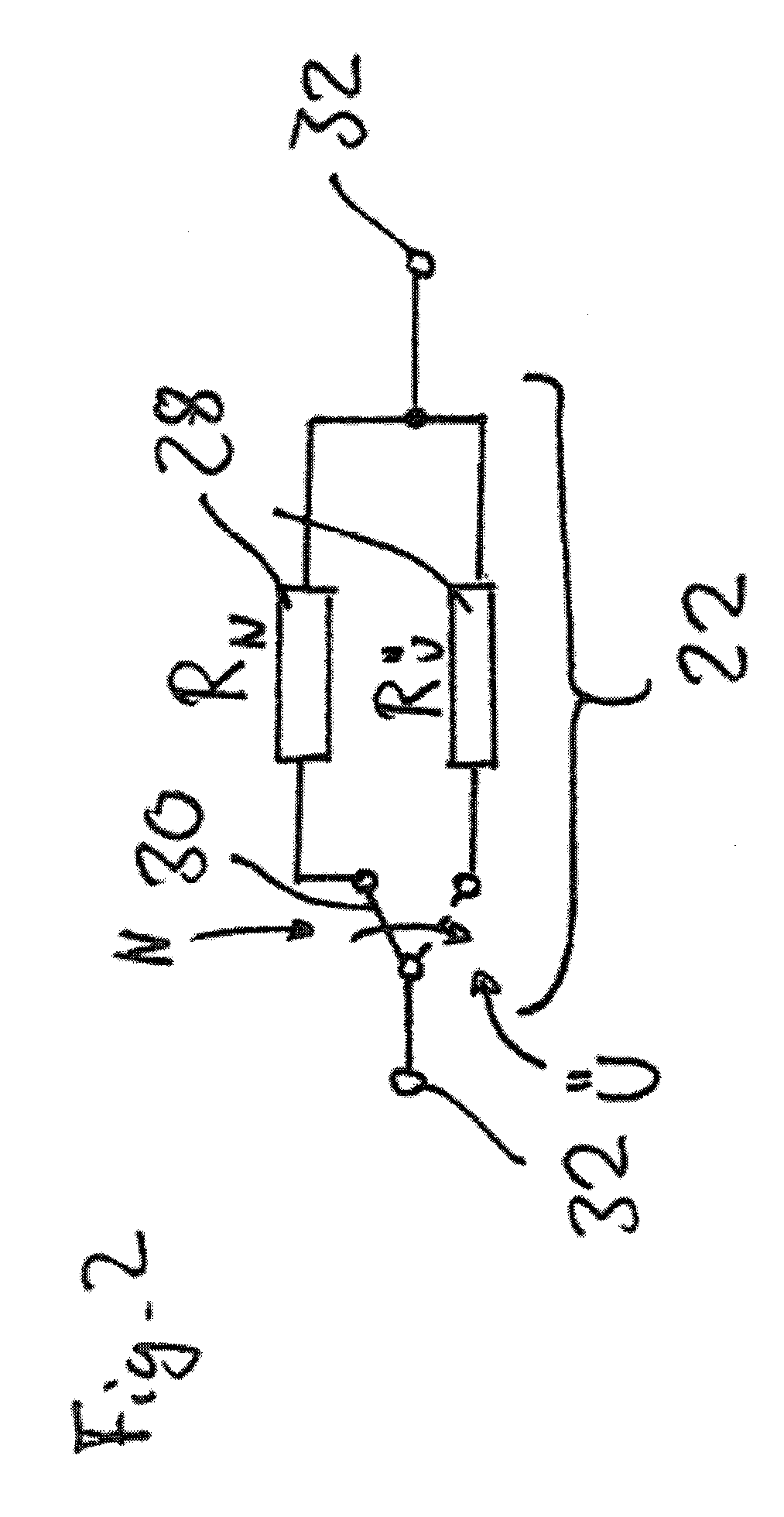
[0043]Converter 6 additionally contains a controller 20, which drives respective switching inputs 18 of semiconductor switches 14. Each switching input 18 is connected to controller 20 via a resistor 22. Controller 20 includes a voltage source 21 ...


PUM


Abstract

A solar module has a solar cell which generates a DC voltage. The module has a converter for converting a DC voltage fed into its input. The module contains a semiconductor switch and a controller which drives a switching input of the semiconductor switch. The controller drives the semiconductor switch variably so that the semiconductor switch switches more slowly during the transition operation than during normal operation, thereby reducing a dynamic overvoltage on the switch such that the voltage present on the switch does not exceed the blocking voltage of the switch.

Description

BACKGROUND OF THE INVENTION[0001]1. Field of the Invention[0002]The invention relates to a solar module, comprising a solar cell and a converter, and to a method for its operation.[0003]2. Description of the Related Art[0004]Solar cells are commonly used to generate regenerative energy. To prepare the DC voltage generated by the solar cells for use, for example in a power supply network, they are combined with a converter, generally an inverter, to form a solar module. The converter converts the DC voltage received by the converter from the solar cells into an AC voltage which is in turn supplied to the power supply network. The solar cell generally mentioned in the singular here in practice often comprises a plurality of individual solar cells connected in series. In a known, simple embodiment, the converter has at least two transistor half bridges. Each half bridge contains then at least two transistors with at least two freewheeling diodes. Further semiconductors can be located b...

Claims


Application Information

Patent Timeline
Patent Type & Authority Applications(United States)
IPC IPC(8): H02M1/32H02H7/122
CPCH01L31/02021Y02E10/563H02M7/53871H02M1/32H03K17/163H02S40/32H02J3/383H02M2001/0045H02M1/08H02M1/36H02J2300/24H02J3/381Y02E10/56H02M1/0029H02M1/0045G05F1/67H02M7/48
Inventor WEISS, RAINERBECKEDAHL, PETERSTAUDT, INGO
Owner SEMIKRON ELECTRONICS GMBH & CO KG
Why Eureka
Try Eureka