Method for manufacturing heat dissipating apparatus

a technology of heat dissipation apparatus and manufacturing method, which is applied in the direction of lighting and heating apparatus, indirect heat exchanger, basic electric elements, etc., can solve the problems of permanent damage to humans or the environment, and the increase of heat generated by electronic components

Inactive Publication Date: 2012-12-20
FU ZHUN PRECISION IND SHENZHEN +1
View PDF11 Cites 3 Cited by
  • Summary
  • Abstract
  • Description
  • Claims
  • Application Information

AI Technical Summary

Problems solved by technology

However, such electronic components generate increased levels of heat, which must be dissipated promptly.
However, solder is typically composed of a lot of heavy metals, such as lead, tin or others, which if mishandled can cause permanent damage to humans or the environment.

Method used


Image

  • Method for manufacturing heat dissipating apparatus
  • Method for manufacturing heat dissipating apparatus
  • Method for manufacturing heat dissipating apparatus

Examples


first embodiment

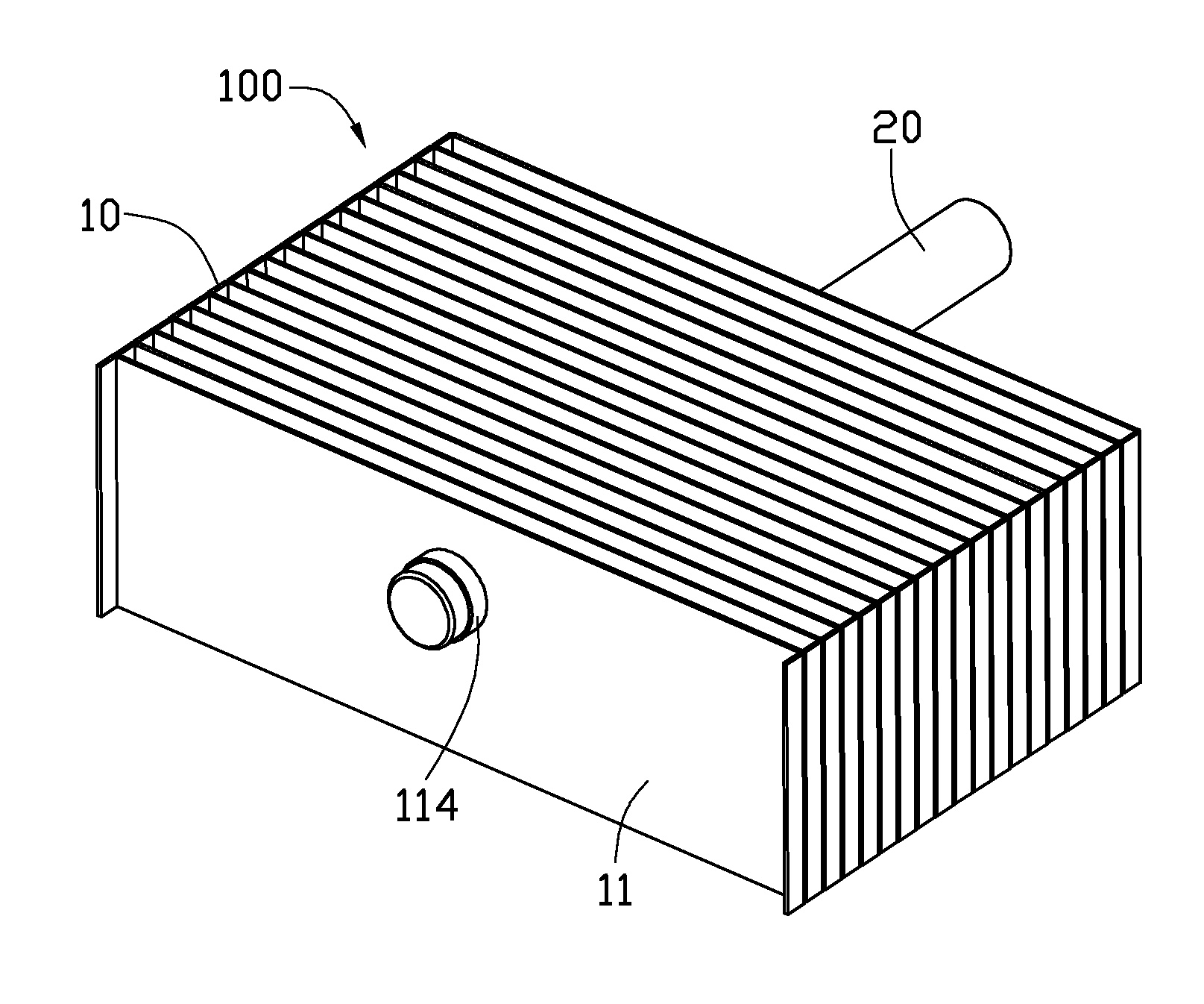
[0012]Referring to FIG. 1, a heat dissipation apparatus 100 manufactured through a manufacturing method in accordance with the present disclosure is shown. The heat dissipation apparatus 100 includes a fin assembly 10, and a heat pipe 20 extending through the fin assembly 10.

[0013]The fin assembly 10 includes a plurality of plate-shaped metallic fins 11 stacked together and spaced apart from each other at constant intervals. An air passage is defined between every two adjacent fins 11. Each of the fins 11 is rectangular and defines a through hole 112 therein, for extending of the heat pipe 20 therethrough. The through holes 112 are circular. An annular collar 114 extends perpendicularly from each fin 11 at an edge of the through hole 112. The heat pipe 20 is interferentially fixed in the collar 114 of each fin 11 (see below).

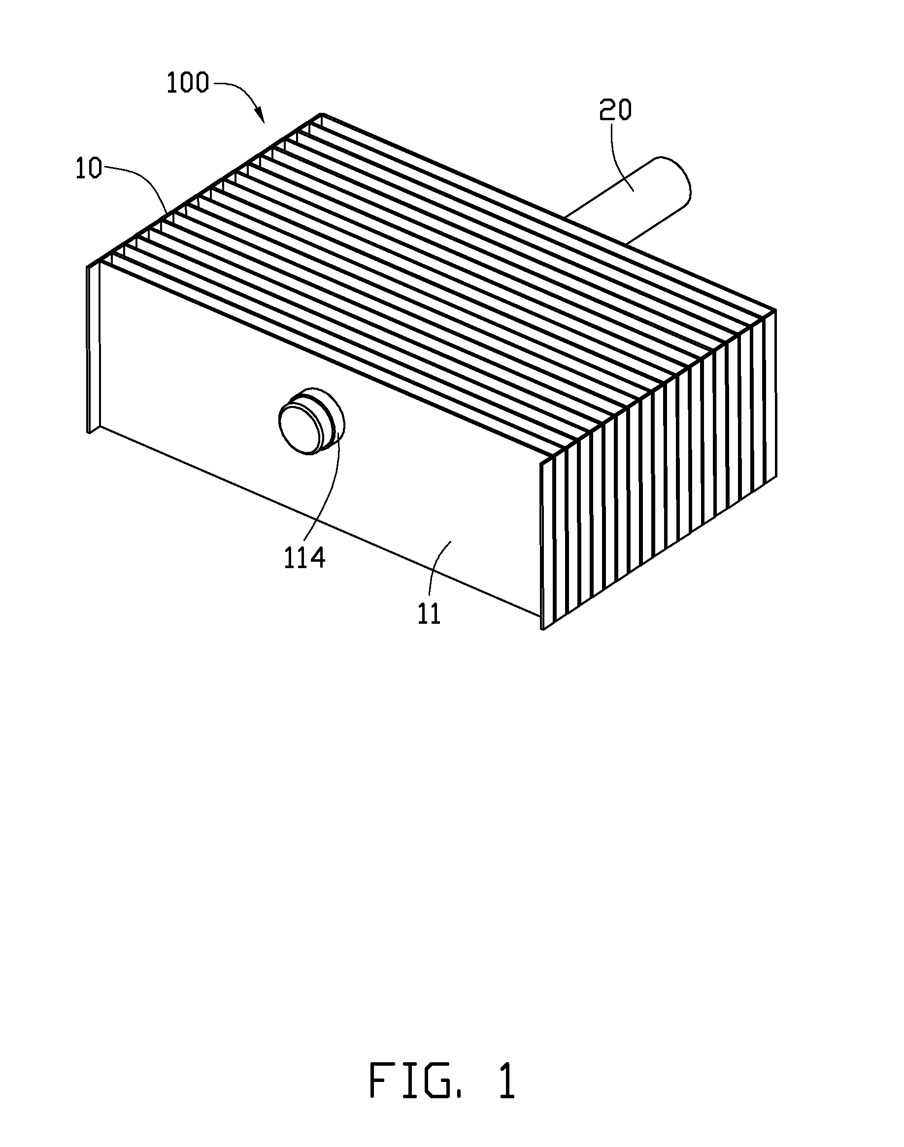
[0014]Referring also to FIGS. 2 and 3, during manufacturing of the heat dissipation apparatus 100, a first punching tool 40, a second punching tool 50 and a pun...

second embodiment

[0021]Referring to FIG. 6, this is a schematic view of a single step of a method for manufacturing the heat dissipation apparatus 100 in accordance with the present disclosure. In this embodiment, the first punching tool 40 is placed above the second punching tool 50, and the fin assembly 10 is prefixed on the second punching tool 50. By this arrangement, each fin 11 of the fin assembly 10 is located between every two adjacent two punching units 52 of the second punching tool 50, and the collar 114 of each fin 11 is held in a recess 521 of a corresponding punching unit 52 of the second punching tool 50. The first punching tool 40 is driven by a punch (not shown) to punch the fin assembly 10 fixed on the second punching tool 50, similar to the procedure shown in FIG. 4 and FIG. 5.

third embodiment

[0022]Referring to FIG. 7, this is a front view of part of a heat dissipation apparatus 100a before a punching process of a method for manufacturing the heat dissipation apparatus 100a in accordance with the present disclosure. In this embodiment, a collar 114a of each fin 11a of the heat dissipation apparatus 100a defines two slots 114l therein. Each of the slots 114l is strip-shaped, and extends parallel to an axis of the collar 114a. The two slots 114l of the collar 114a face each other to divide the collar 114a into two equal parts. This allows the collar 114a to shrink more easily during the punching process. When the punching process is completed, the two slots 114l of the collar 114a are substantially closed due to the shrinkage of the collar 114a. In this embodiment, the collar 114a defines two slots 114l. Understandably, in other embodiments, one slot 114l or more than two slots 114l can be defined in the collar 114a.


PUM

PropertyMeasurementUnit
outer diameteraaaaaaaaaa
diameteraaaaaaaaaa
inner diameteraaaaaaaaaa

Abstract

An exemplary method for manufacturing a heat dissipation apparatus includes, firstly, providing a fin assembly including a stack of fins spaced from each other. Each fin defines a through hole therein, and includes a collar formed at an edge of the through hole. Then a heat pipe is provided, and inserted in the through holes of the fins. Next, two opposing punching tools are provided. Each punching tool defines a series of recesses. The subassembly of the heat pipe and fins is positioned between the two punching tools, with the collar of each fin located between two corresponding recesses of the two punching tools. The two punching tools punch the collars of the fins from two opposite sides of the collars. Thereby, the collars shrink inwardly and press the heat pipe to deform until the heat pipe is fittedly mounted in the collars of the fins.

Description

BACKGROUND[0001]1. Technical Field[0002]The present disclosure generally relates to methods for manufacturing heat dissipation apparatuses, and particularly to a method for manufacturing a heat dissipation apparatus having a heat pipe.[0003]2. Description of Related Art[0004]With developments in electronics technology, increased performance of electronic components such as CPUs (central processing units) has been achieved. However, such electronic components generate increased levels of heat, which must be dissipated promptly. Conventionally, a heat dissipation apparatus which includes a fin assembly combined with a heat pipe is used to remove the heat generated by the electronic component.[0005]The fin assembly includes a plurality of fins. Each fin defines a through hole therein, for extending of the heat pipe therethrough. In order to ensure a high heat conductive efficiency between the heat pipe and the fins, typically, the heat pipe is soldered in the through holes of the fins ...

Claims


Application Information

Patent Timeline
Patent Type & Authority Applications(United States)
IPC IPC(8): B21D53/02
CPCH01L23/3672H01L23/427H01L21/4882H01L2924/0002Y10T29/49913Y10T29/49373Y10T29/4935H01L2924/00F28D15/0275F28F1/24F28F2275/12
Inventor ZHANG, JINGLIU, JIANHE, XING-HUA
Owner FU ZHUN PRECISION IND SHENZHEN
Why Eureka
Try Eureka