Solid-state imaging element, solid-state imaging device, imaging apparatus, and method of manufacturing polarizing element

a technology of solid-state imaging and elements, which is applied in the direction of polarizing elements, radiofrequency control devices, instruments, etc., can solve the problems of difficult application of such a technique to an imaging device having a small pixel size, and achieve the effects of reducing the thickness of the solid-state imaging element, simple configuration and structure, and excellent extinction characteristics

Active Publication Date: 2012-12-20
SONY CORP
View PDF4 Cites 60 Cited by
  • Summary
  • Abstract
  • Description
  • Claims
  • Application Information

AI Technical Summary

Benefits of technology

[0031]An absorption-type polarizing element in the solid-state imaging element and the like of the present invention, employing a wire grid polarizer technique has a stacked structure in which a stripe-shaped reflecting layer, an insulating layer formed on the reflecting layer, and a light absorption layer made up of a plurality of segments formed on the insulating layer in a separated state are stacked in that order from the photoelectric conversion element side. Thus, it is possible to provide a polarizing element which has a desired polarization orientation and excellent extinction characteristics with a simple configuration and structure. In addition, since polarizing elements are integrally formed above the photoelectric conversion element in an on-chip form, it is possible to decrease the thickness of the solid-state imaging elemen

Problems solved by technology

However, since the photonic crystal array is manufactured separately from the solid-state imaging element and both

Method used


Image

  • Solid-state imaging element, solid-state imaging device, imaging apparatus, and method of manufacturing polarizing element
  • Solid-state imaging element, solid-state imaging device, imaging apparatus, and method of manufacturing polarizing element
  • Solid-state imaging element, solid-state imaging device, imaging apparatus, and method of manufacturing polarizing element

Examples


first embodiment

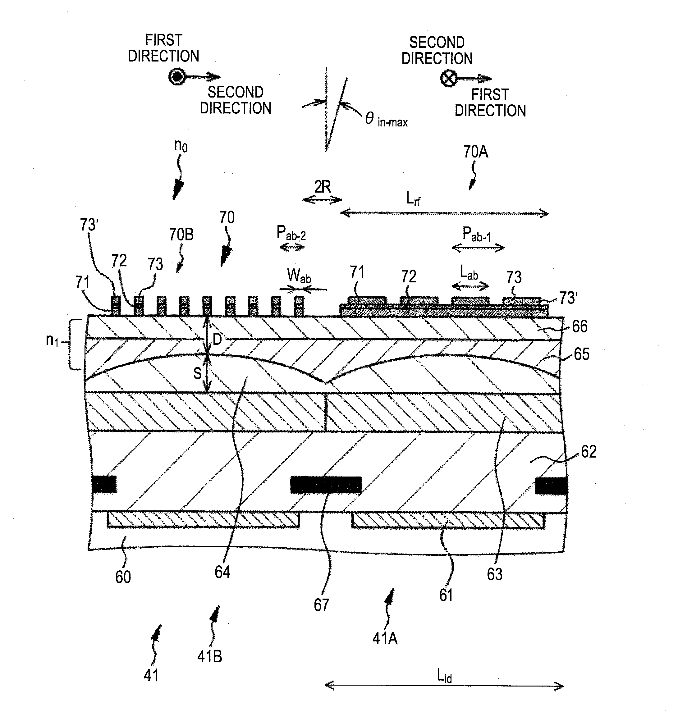
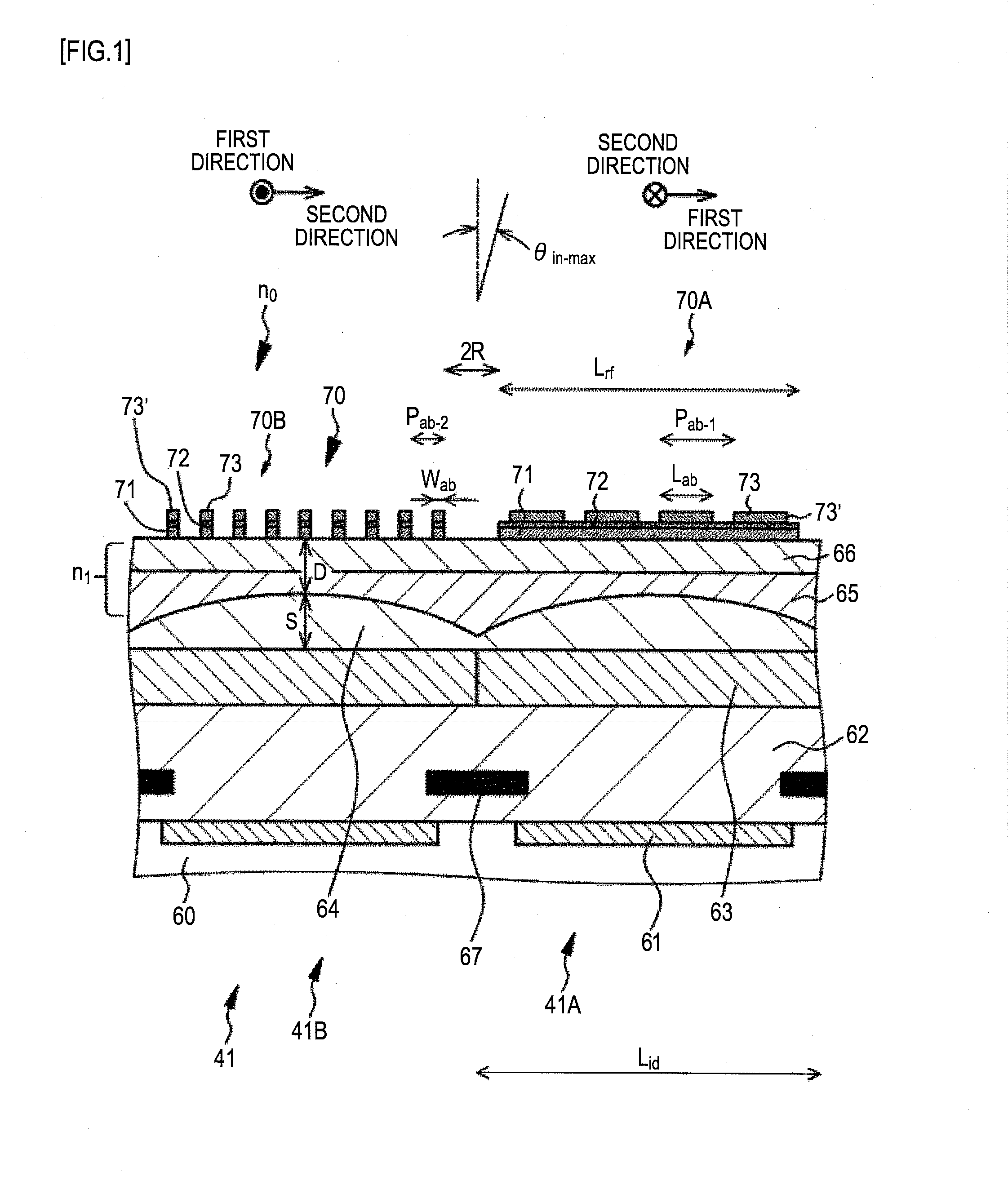
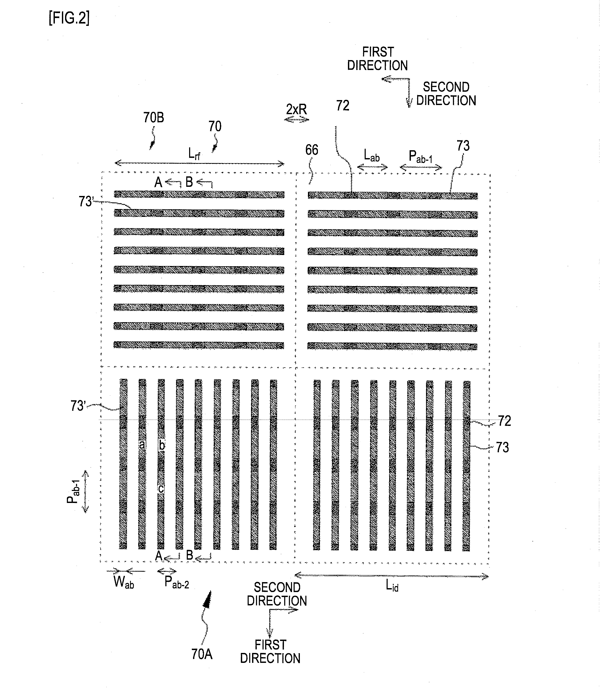
[0154]A first embodiment relates to a solid-state imaging element of the invention, a solid-state imaging device of the invention, an imaging apparatus of the present invention, and a polarizing element manufacturing method. More specifically, the first embodiment relates to the solid-state imaging element A of the present invention. A schematic partial cross-sectional view of a solid-state imaging element constituting the solid-state imaging device of the first embodiment is shown in FIG. 1, and a schematic partial plan view of the solid-state imaging element is shown in FIG. 2. A schematic partial cross-sectional view of a polarizing element is shown in (A) and (B) in FIG. 32. Two solid-state imaging elements are shown in FIG. 1, and four solid-state imaging elements are shown in FIG. 2. FIG. 1 is a schematic partial cross-sectional view taken along the arrows A-A in FIG. 2 and shows a schematic partial cross-sectional view of a solid-state imaging element along the extension dire...

second embodiment

[0188]The second embodiment is a modification of the first embodiment. The ADL method can form a film on the side surface of the polarizing element 70 more conformally than the CVD method. Thus, it is possible to prevent deterioration of optical characteristics of polarizing elements. In particular, a protective film formed of a metal oxide such as AlOx or HfOx has a high ability to protect a polarizing element and can form a film conformally in a small thickness. Therefore, such a protective film can function as a good protective film which does not deteriorate optical characteristics.

[0189]In the second embodiment, the polarizing element 70 is formed so that the formation pitch Pab-2 along the second direction is 180 nm, the width Wab is 80 nm, and the space Pab-2-Wab between the polarizing element 70 and the polarizing element 70 is 100 nm. Specifically, in the second embodiment, in the same step as Step-130 of the first embodiment, after removing the etching mask layer 92, a pro...

third embodiment

[0191]The third embodiment is a modification of the second embodiment. In the second embodiment, the protective film 74 was also formed on the inorganic insulating base layer 66 where the polarizing element 70 is not formed. However, a further characteristic improvement (specifically, a further improvement of sensitivity) can be attained when the protective film 74 is not formed on the inorganic insulating base layer 66 where the polarizing element 70 is not formed.

[0192]In the third embodiment, in the same step as “Step-130” of the first embodiment, after removing the etching mask layer 92, a protective film 74 formed of AlOx or HfOx is formed on the polarizing element 70 (more specifically, the polarizing element 70 and the inorganic insulating base layer 66) based on the ADL method similarly to the second embodiment. Here, the protective film 74 is formed so that the thickness on the side surface of the polarizing element 70 is 15 nm (see the schematic partial cross-sectional vie...


PUM


Abstract

The present invention relates to a solid-state imaging element which is able to provide the solid-state imaging element having a polarizing element having a simple configuration and structure based on a wire grid polarizer technique, a solid-state imaging device, an imaging apparatus, and a method of manufacturing a polarizing element. The solid-state imaging device includes a plurality of solid-state imaging elements 41 each including a photoelectric conversion element 61 and a polarizing element 70 formed on the light incident side of the photoelectric conversion element 61. The solid-state imaging device includes two or more kinds of polarizing elements 70 having different polarization orientations. Each polarizing element has a stacked structure in which a stripe-shaped reflecting layer 71, an insulating layer 72 formed on the reflecting layer 71, and a light absorption layer 73 made up of a plurality of segments 73′ formed on the insulating layer 72 in a separated state are stacked in that order from the photoelectric conversion element side.

Description

TECHNICAL FIELD[0001]The present invention relates to a solid-state imaging element, a solid-state imaging device, an imaging apparatus, and a method of manufacturing a polarizing element.BACKGROUND ART[0002]Optical elements in which polarizing elements having different polarization orientations are disposed in each small region and electronic devices in which such optical elements are integrated are commercialized around a display device and a measuring device. For example, Xpol (registered trademark) manufactured by Arisawa Manufacturing Co., Ltd. is sold as a display device.[0003]As disclosed in JP-A-2004-309868, an imaging device is known which includes: imaging means in which pixels corresponding to an integer multiple of a predetermined number of scanning lines are formed on an imaging surface; first horizontal component polarizing means that transmits only horizontal components of first video light from a subject; and first vertical component polarizing means that is disposed...

Claims


Application Information

Patent Timeline
IPC IPC(8): H01L31/0232B44C1/22G02B30/25G03B17/12
CPCH01L27/14605H01L27/14621H01L27/14629H01L27/14627H01L27/14625H01L27/146G02B5/30
Inventor OZAWA, KENOOKA, YUTAKAOTANI, EIJI
Owner SONY CORP
Why Eureka
Try Eureka