
System and method for thermal energy storage and power generation

a technology of thermal energy storage and power generation, applied in the direction of indirect heat exchangers, machines/engines, lighting and heating apparatus, etc., can solve the problems of reduced reliability of equipment, increased emissions, and insufficient pumped hydro sites available, so as to facilitate the transport of energy transfer media

Inactive Publication Date: 2012-12-20
WOODWARD GOVERNOR CO
View PDF22 Cites 125 Cited by
  • Summary
  • Abstract
  • Description
  • Claims
  • Application Information

AI Technical Summary

Benefits of technology

The present invention is a system for storing and providing electrical output from thermal energy. The system includes an insulated containment vessel with a thermal conductive endostructure and a thermal energy storage media. The thermal conductive endostructure absorbs and conducts heat from a source energy to the thermal energy storage media. The system also includes a heat exchanger that transfers the stored thermal energy to an energy transfer media, which then converts the heat into work and exhaust. The system can provide electrical output through a primary and secondary thermal energy conversion process. The technical effects of the invention include efficient storage and utilization of thermal energy, improved energy conversion efficiency, and reduced waste heat production.

Problems solved by technology

Presently, fossil fuel resources are ramped up and down to balance the variability of wind and solar generation, resulting in increased emissions and reduced reliability of equipment.
Unfortunately, there are not sufficient pumped hydro sites available to relieve grid congestion and the ramp-up time required for such systems is substantial.
Battery technologies are being demonstrated, however costs are high and reliability is untested over long periods.
Prior implementations of Thermal Energy Storage (TES) have seen limited success.
For grid scale, TES has seen limited application, and primarily for direct application in concentrated solar power (CSP) utilizing very large storage vessels of molten salt.
These single-phase, molten salts have typically been designed to have a low melting point because they require pumping through closed loop systems and failure modes often involve solidification of the molten salt within the system, resulting in significant effort to re-liquefy the entire heat transfer circuit upon restart.

Method used


Image

  • System and method for thermal energy storage and power generation
  • System and method for thermal energy storage and power generation
  • System and method for thermal energy storage and power generation

Examples


Embodiment Construction

[0015]While this invention is susceptible to embodiment in many different forms, it is shown in the drawings, and will be described herein in detail, specific embodiments thereof with the understanding that the present disclosure is to be considered as an exemplification of the principles of the invention and is not to be limited to the specific embodiments described.

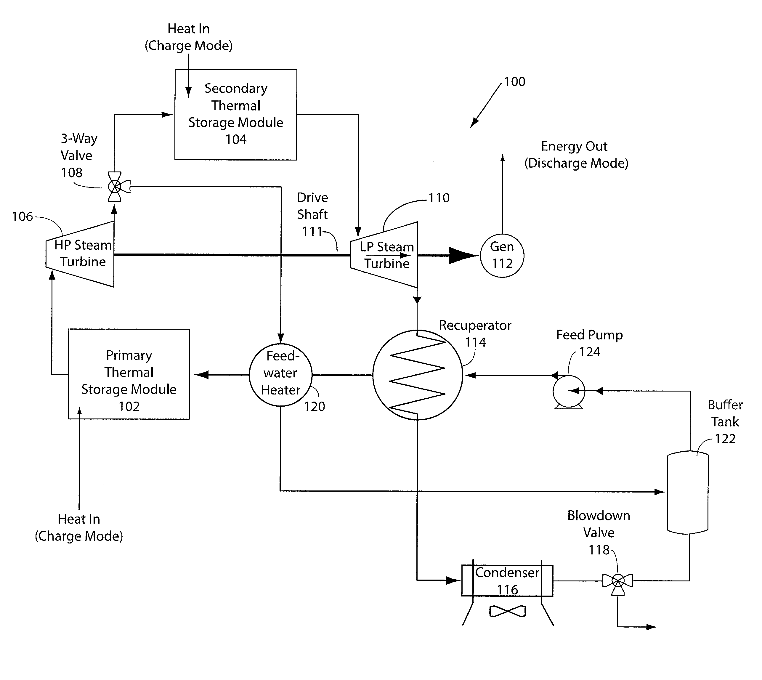
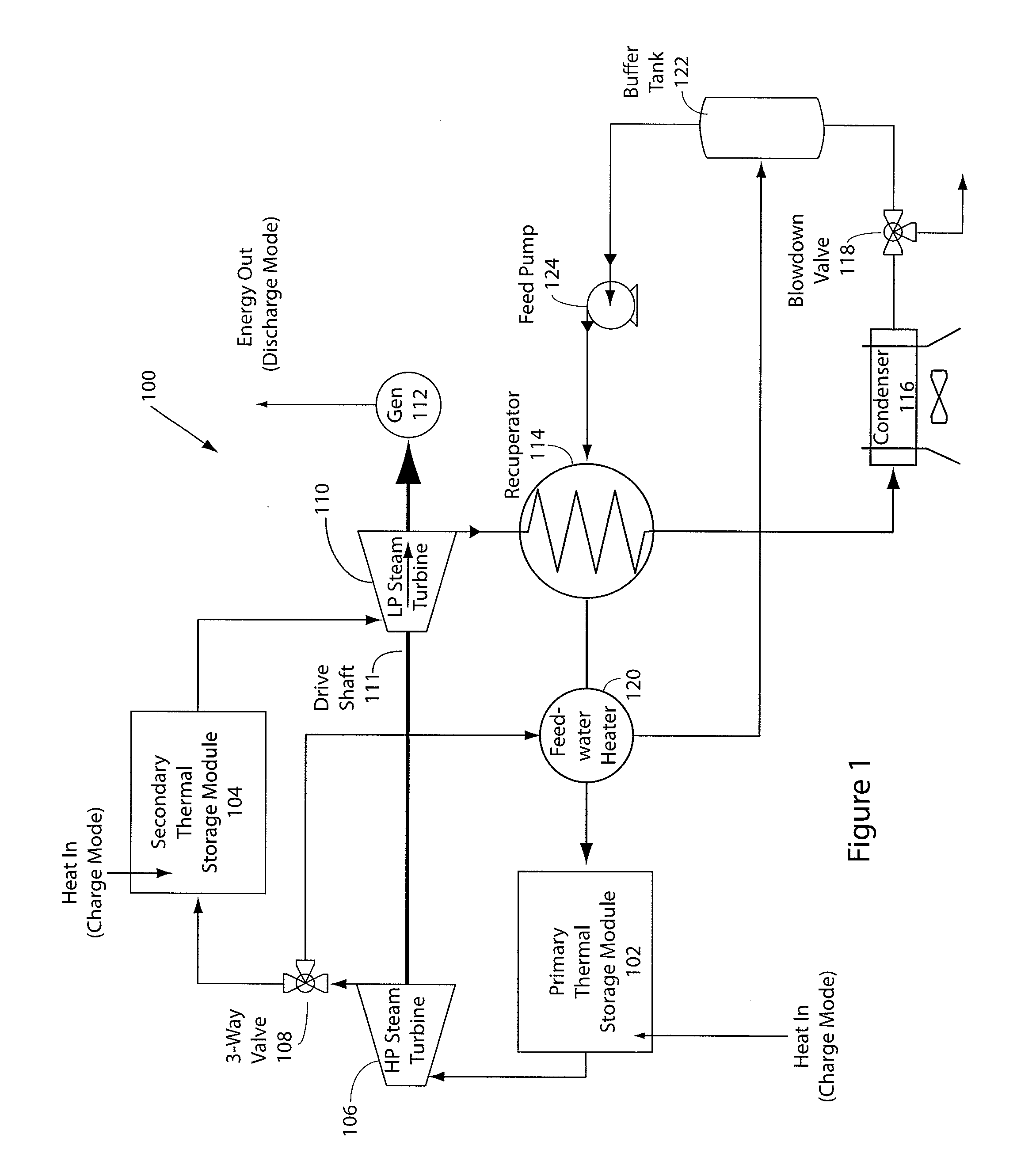
[0016]FIG. 1 illustrates an embodiment of a system for storing thermal energy storage and later utilizing this stored energy to generate power with a steam turbine generator. The exemplary embodiment of the steam turbine TES system 100 depicted in FIG. 1, provides a system that stores thermal energy utilizing materials of various specific heats and latent heats of fusion, and melting / freezing temperature ranges across a temperature range that is advantageous for providing turbine driven power generation while being able to “charge” (bring the TES media to maximum operational temperature) within a short specified period....


PUM


Abstract

A thermal energy storage system is proposed in which the latent heat of fusion of common salts is used to store energy within a selectable temperature range, extending both above and below the melting / freezing temperature zone of the salt mixture. The salt mixture occupies interstitial void spaces in a solid endostructure. The solid material remains in the solid state throughout the thermal cycling of the energy storage system, and preferably has properties of thermal conduction and specific heat that enhance the behavior of the salt mixture alone, while being chemically compatible with all materials in the storage system. The storage system is capable of accepting and delivering heat at high rates, thereby allowing power generation using a suitable energy transfer media to power a turbine of an electric generator or a process heat need to provide a relatively local, dispatchable, rechargeable thermal storage system, combined with a suitably sized generator.

Description

BACKGROUND OF THE INVENTION[0001]With the increasing integration of renewable generation and the resulting stress on grid reliability, new, low cost, robust methods are needed to store power for buffering excess off-peak generation and balancing of electrical supply and demand. Presently, fossil fuel resources are ramped up and down to balance the variability of wind and solar generation, resulting in increased emissions and reduced reliability of equipment. Pumped hydroelectric storage is an example of the ability to charge a storage system during off-peak operation, and maintain availability to produce peak power on demand. Unfortunately, there are not sufficient pumped hydro sites available to relieve grid congestion and the ramp-up time required for such systems is substantial. Battery technologies are being demonstrated, however costs are high and reliability is untested over long periods.[0002]Prior implementations of Thermal Energy Storage (TES) have seen limited success. For...

Claims


Application Information

Patent Timeline
Patent Type & Authority Applications(United States)
IPC IPC(8): H02K7/18
CPCF02C1/05F02C6/10F05D2260/42Y02E60/145F22B1/028F28F13/00F28D20/021F01K3/00Y02E60/14
Inventor AMBROSEK, JAMES W.ANDERSON, MARK H.BROOKS, PAULRILEY, MICHAEL B.FIELD, GREG W.EFTEKHARI SHAHROUDI, KAMRANNELEN, RICHARD JJGENDRON, THOMAS A.KAISER, GARY F.
Owner WOODWARD GOVERNOR CO
Learn More