
Driving Method and a Display Panel using the method

Active Publication Date: 2012-12-20
LIU HUNG TA
View PDF7 Cites 28 Cited by
  • Summary
  • Abstract
  • Description
  • Claims
  • Application Information

AI Technical Summary

Benefits of technology

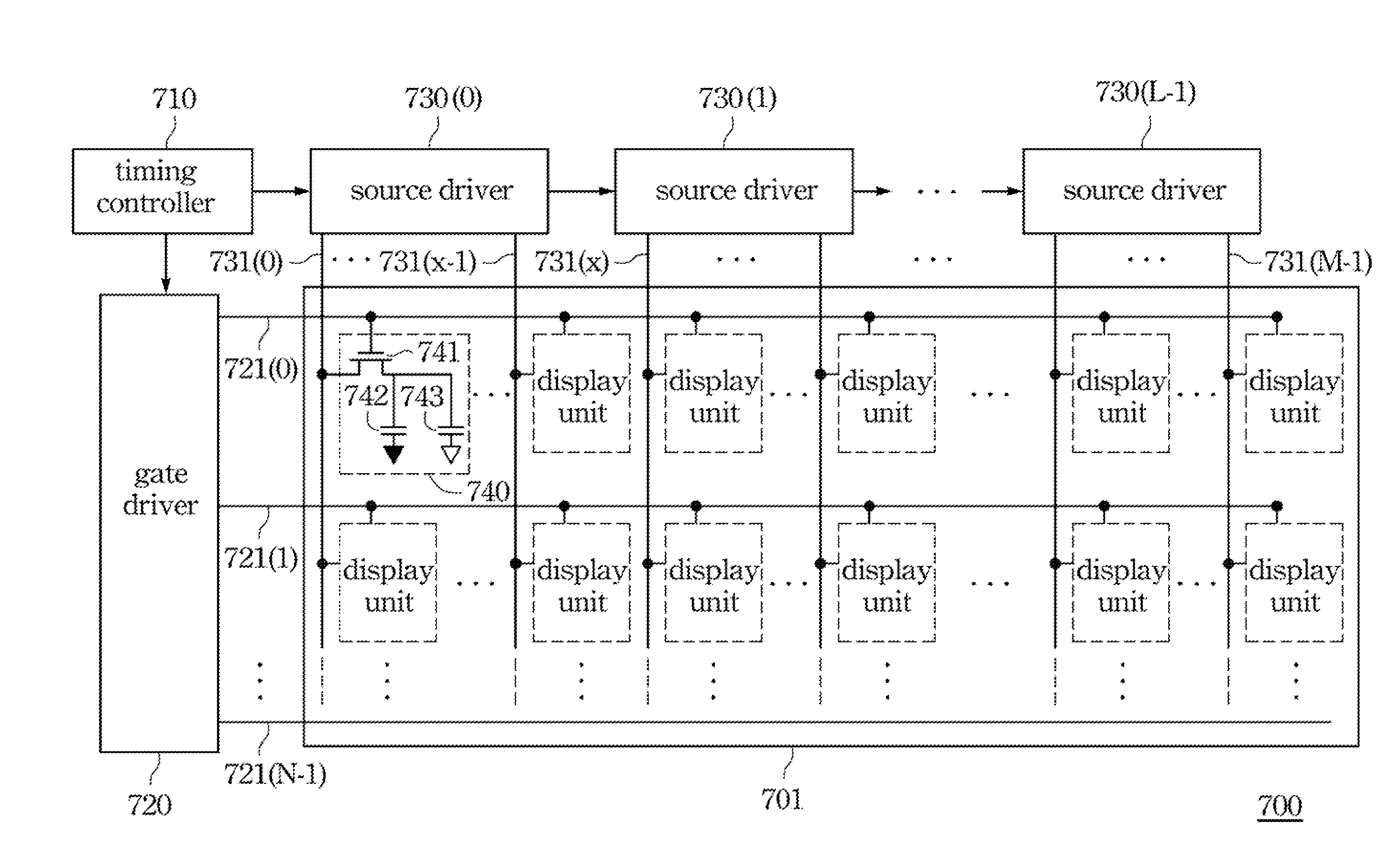
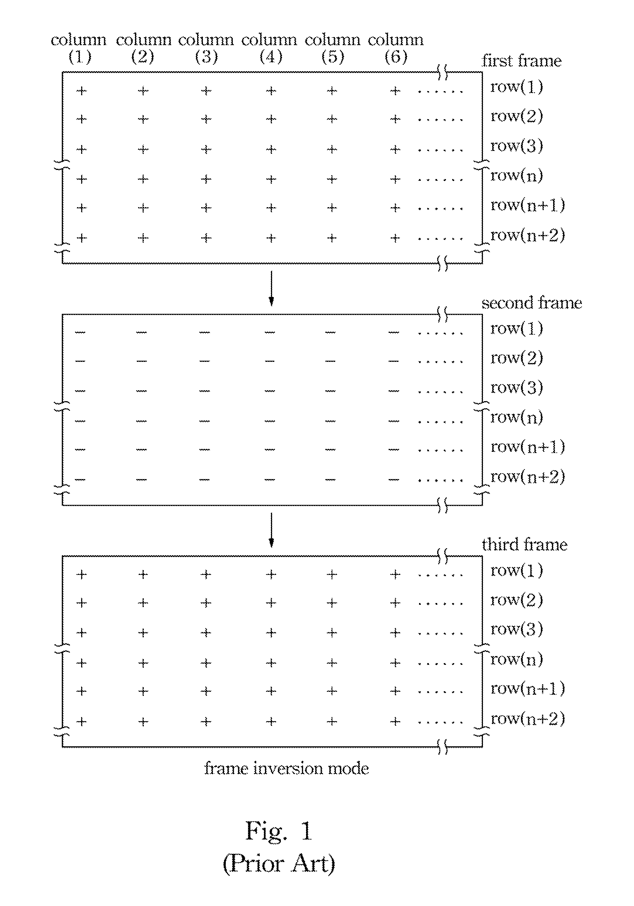
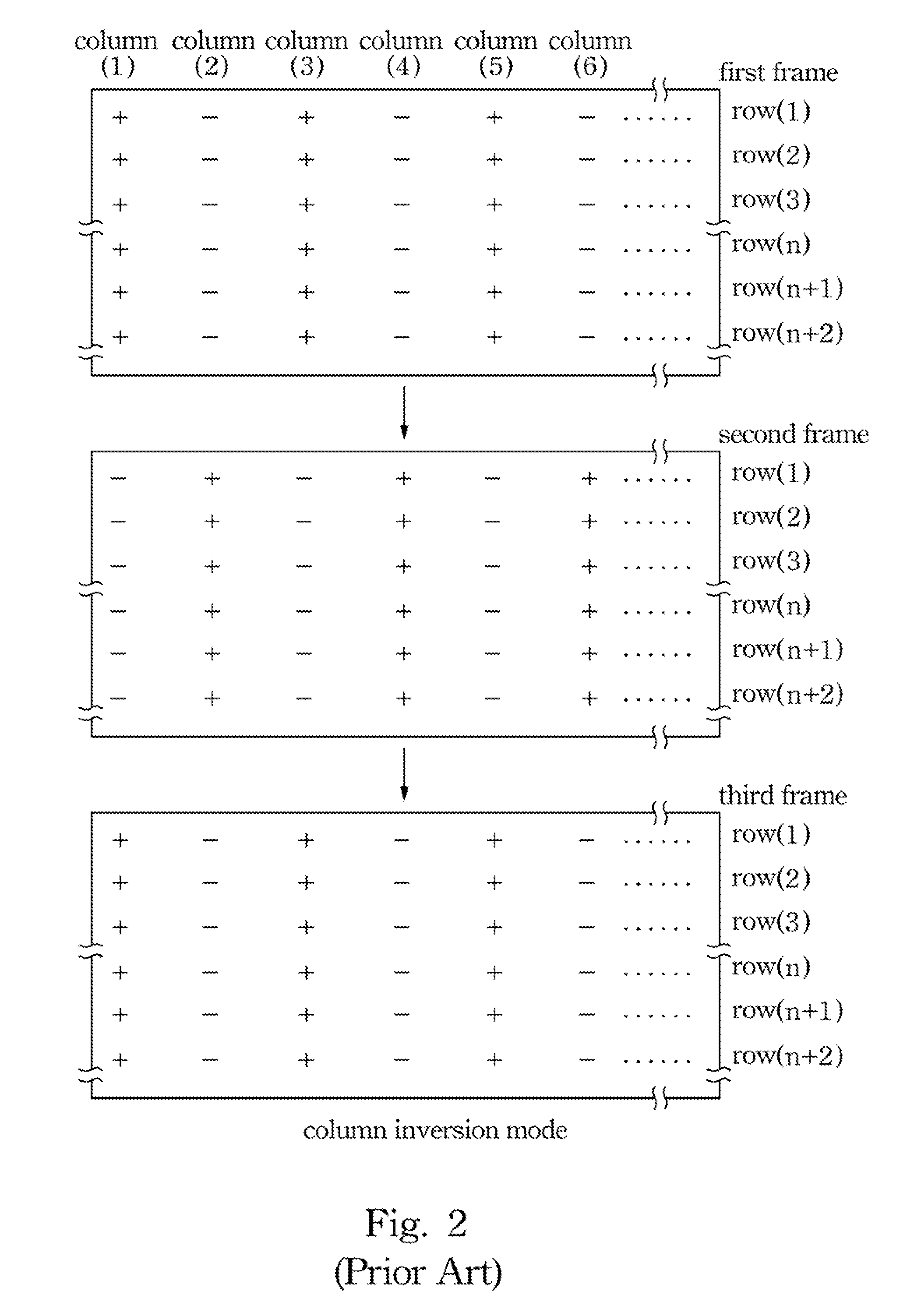
[0012]One aspect of the present invention is to provide a driving method for a display. The driving method reduces the number of the polarity of pixels changed from positive (+) to negative (−) or from negative (−) to positive (+) to reduce the power consumption of a display.
[0013]One aspect of the present invention is to provide a driving method for a display. The driving method reduces the work time of the gate driver and / or the source driver to reduce power consumption of a display. When the gate driver or the source driver is not operated in a working state, the drive voltage or drive current supplied to the gate driver or the source driver is reduced or is stopped. Therefore, the power consumption may be reduced. Moreover, by this way, the refresh rate is also reduced.
[0014]One aspect of the present invention is to provide a driving method for a display or a liquid crystal display. The driving method reduces the power supplied to the source driver to reduce power consumption of a display. Moreover, by this way, the refresh rate is also reduced.
[0050]Accordingly, the driving method for a display reduces the number of the polarity of pixels changed from positive (+) to negative (−) or from negative (−) to positive (+) to reduce the power consumption of a display. Moreover, the frame is also divided into at least two time periods, the first time period and the second time period. In the first time period, the gate driver or the source driver is operated in a working state. In the second time period, the gate driver or the source driver is operated in a sleeping state or in a non-working state. The source driver sends the data signal to the pixels only when the gate driver scans the scan lines in the pixels. That is, the source driver does not send any data signal to the pixels when the gate driver does not scan the scan lines in the pixels. In other words, the voltage and the current supplied to the source driver and the gate driver are reduced. Therefore, the power consumption is reduced.

Problems solved by technology

Such driving modes increases overall power consumption of the display panel system.
Such refresh rate causes additional power consumption.

Method used


Image

  • Driving Method and a Display Panel using the method
  • Driving Method and a Display Panel using the method
  • Driving Method and a Display Panel using the method

Examples


Embodiment Construction

[0064]Reference will now be made in detail to the present embodiments of the invention, examples of which are illustrated in the accompanying drawings. Wherever possible, the same reference numbers are used in the drawings and the description to refer to the same or like parts.

[0065]For reducing the power consumption of a liquid crystal display, the driving method of the present invention reduces the number of the polarity of pixels changed from positive (+) to negative (−) or from negative (−) to positive (+). Moreover, the driving method of the present invention also divides the frame into at least two time periods, the first time period and the second time period. In the first time period, the gate driver or / and the source driver is operated in a working state. In the second time period, the gate driver or / and the source driver is operated in a sleeping or in a non-working state. The source driver sends the data signal to the pixels only when the gate driver scans the scan lines ...


PUM


Abstract

A driving method for a display is provided. This display includes a first driver, a second driver, a plurality of first signal lines coupling with the first driver, and a plurality of second signal lines coupling with the second driver. The first lines cross the second lines to form a pixel array with a plurality of pixels. The driving method includes the following steps. First, an image signal with a polarity is applied to the pixel array. The polarity is a first polarity or a second polarity opposite to the first polarity. Then, the image signal applied to at least one pixel of the pixel array is maintained in a same polarity during two successive frames.

Description

RELATED APPLICATIONS[0001]This application is a continuation-in-part of U.S. application Ser. No. 13 / 338,250, filed Dec. 28, 2011, which claims priority to Taiwan Application Serial Number 099147378, filed Dec. 31, 2010, currently pending. The present application is also based on, and claims priority from Taiwan Application Serial Number 100131366 filed Aug. 31, 2011. All of these applications are incorporated herein by this reference.BACKGROUND[0002]1. Field of Invention[0003]The present invention relates to a driving method, and more particularly to a driving Method and a display panel using the method.[0004]2. Description of Related Art[0005]A liquid crystal display utilizes liquid crystal molecules to control light transmission in each pixel. The liquid crystal molecules are driven according to external video signals received by the liquid crystal display. A conventional liquid crystal display generally employs a selected one of a frame inversion mode, a column inversion mode, a...

Claims


Application Information

Patent Timeline
IPC IPC(8): G06F3/038
CPCG02F1/134363G02F1/136213G02F2001/134372G09G3/3648G09G2320/10G09G2330/021G09G2340/0435G09G3/3614G02F1/134372
Inventor LIU, HUNG-TA
Owner LIU HUNG TA
Learn More