Display apparatus

Inactive Publication Date: 2012-12-20
CANON KK
View PDF1 Cites 60 Cited by
  • Summary
  • Abstract
  • Description
  • Claims
  • Application Information

AI Technical Summary

Benefits of technology

[0016]In the display apparatus according to the present aspect, each row has a plurality of row selection lines assigned to respective colors, and the supplying of light-emission data or no-light-emission data via the data lines and the supplying of only no-light-emission data are performed in different non-overlapping periods such that the operation of turning into the light emission state is not coincident with the operation of turning

Problems solved by technology

The provision of such additional control lines results in a reduction in layout space in which circuit elements such as transistors, capacitors,

Method used


Image

  • Display apparatus
  • Display apparatus
  • Display apparatus

Examples


Example

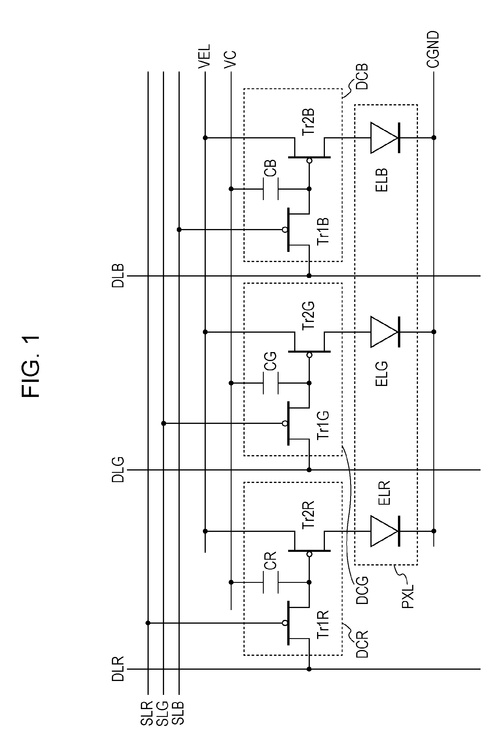
[0025]FIG. 1 is a circuit diagram illustrating a structure of one of pixels of an organic electroluminescent display apparatus according to an embodiment of the present invention.

[0026]One pixel includes three organic electroluminescent elements each capable of emitting one of light of three colors, i.e., red (R), green (G), and blue (B). Each organic electroluminescent element is connected to an EL driving circuit including a first transistor Tr1, a second transistor Tr2, and a storage capacitor C.

[0027]In FIG. 1, suffixes R, G, and B are used to distinguish among colors associated with circuit elements. In the present description, when an explanation is concerned with a general matter that is not specific to a particular color, no suffix is used.

[0028]In each EL driving circuit DC, as shown in FIG. 1, the transistor Tr1 is connected such that a gate thereof is connected to a row selection line SL, a drain thereof is connected to a data line DL, and a source thereof is connected to...


PUM


Abstract

An exemplary embodiment of the present invention is a display apparatus. In the display apparatus, each row has as many row selection lines as the number of colors of light emitting elements, and row selection signals are supplied via the row selection lines such that a first row selection signal and a second row selection signals are supplied to driving circuits of light emitting elements of each color in first and second periods alternately and a plurality of times at different intervals in each frame. In the first period, light-emission or no-light-emission data signals are supplied over data lines. In the second period, only no-light-emission data signals are supplied. One of the first and second row selection signals is supplied with the same timing for all colors, while the other one of the row selection signals is supplied with timing different among the colors.

Description

BACKGROUND OF THE INVENTION[0001]1. Field of the Invention[0002]The present invention relates to a display apparatus, and more particularly, to a display apparatus using an organic electroluminescence (EL) display element.[0003]2. Description of the Related Art[0004]To achieve gray levels in an image displayed on an active matrix organic electroluminescent display apparatus, it is known to divide one frame period into a plurality of subframe periods, and rewrite data on a subframe-by-subframe basis to control emission of each pixel in each subframe. In the case of a color organic electroluminescent display apparatus, the display apparatus includes a plurality of pixels each including three organic electroluminescent elements capable of emitting light of red (R), green (G), and blue (B), respectively, and a white balance adjustment is performed by changing the ratio of luminance among the three organic electroluminescent elements.[0005]U.S. Patent Application Publication No. 2006 / 020...

Claims


Application Information

Patent Timeline
IPC IPC(8): G09G5/10
CPCG09G3/3225G09G3/3266G09G2320/064
Inventor GODEN, TATSUHITOISEKI, MASAMI
Owner CANON KK
Why Eureka
Try Eureka