Safety brake device for moving machine elements

a safety brake and moving machine technology, applied in the direction of braking system, maintenance and safety accessories, vehicle components, etc., can solve the problems of inability to prevent injuries, inability to fully protect the operator, and considerable residual hazards, etc., to achieve easy maintenance, simple design, and greater protection effect for the operator

Active Publication Date: 2013-01-03
CALLIARI UMBERTO
View PDF10 Cites 9 Cited by
  • Summary
  • Abstract
  • Description
  • Claims
  • Application Information

AI Technical Summary

Benefits of technology

[0008]In order to eliminate the disadvantages described, the invention is therefore based on the problem of creating a safety brake device for moving machine elements which can be used universally and is of simple construction, which is easy to maintain and at the same time offers a greater protective effect for the operator than the previously known safety and protection devices.
[0013]In a second aspect, the present invention is directed to a safety brake device for moving machine elements to prevent injury to the extremities of the operator of a machine when the distance of said operator from the moving machine element is less than a defined safety area, comprising: a detector arranged for detecting the operator's position, in order to permit operation of the machine only if the operator remains within the defined working area; a detector arranged for detecting the position of the operator's extremities within a predefined safety zone which enables the required work activities to be performed; and a brake device capable of immediately stopping the moving machine element if the operator's extremities go beyond the safety area.

Problems solved by technology

These safety devices are in most cases very simple in design and do not offer full protection for the operator, since these only protect parts of the machine elements or tools, or the machine elements have a relatively long stopping time and it is thus still possible to reach into the hazardous area.
Nonetheless, a considerable residual hazard remains since, due to their rotary or kinetic energy, the moving machine elements are not stopped immediately.
Even though the drives of the machines are increasingly equipped with brakes, the stopping times in each case amount to several seconds, which means that injuries cannot be prevented.
However, a disadvantage here is that the aluminum claw needs to be replaced after each use.

Method used


Image

  • Safety brake device for moving machine elements
  • Safety brake device for moving machine elements
  • Safety brake device for moving machine elements

Examples


Embodiment Construction

[0019]This problem is solved by the invention through the features delineated in the claims. Advantageous embodiments thereof are described herein and further in the claims.

[0020]Numerous significant advantages are achieved through the safety brake device according to the invention in comparison with the prior art.

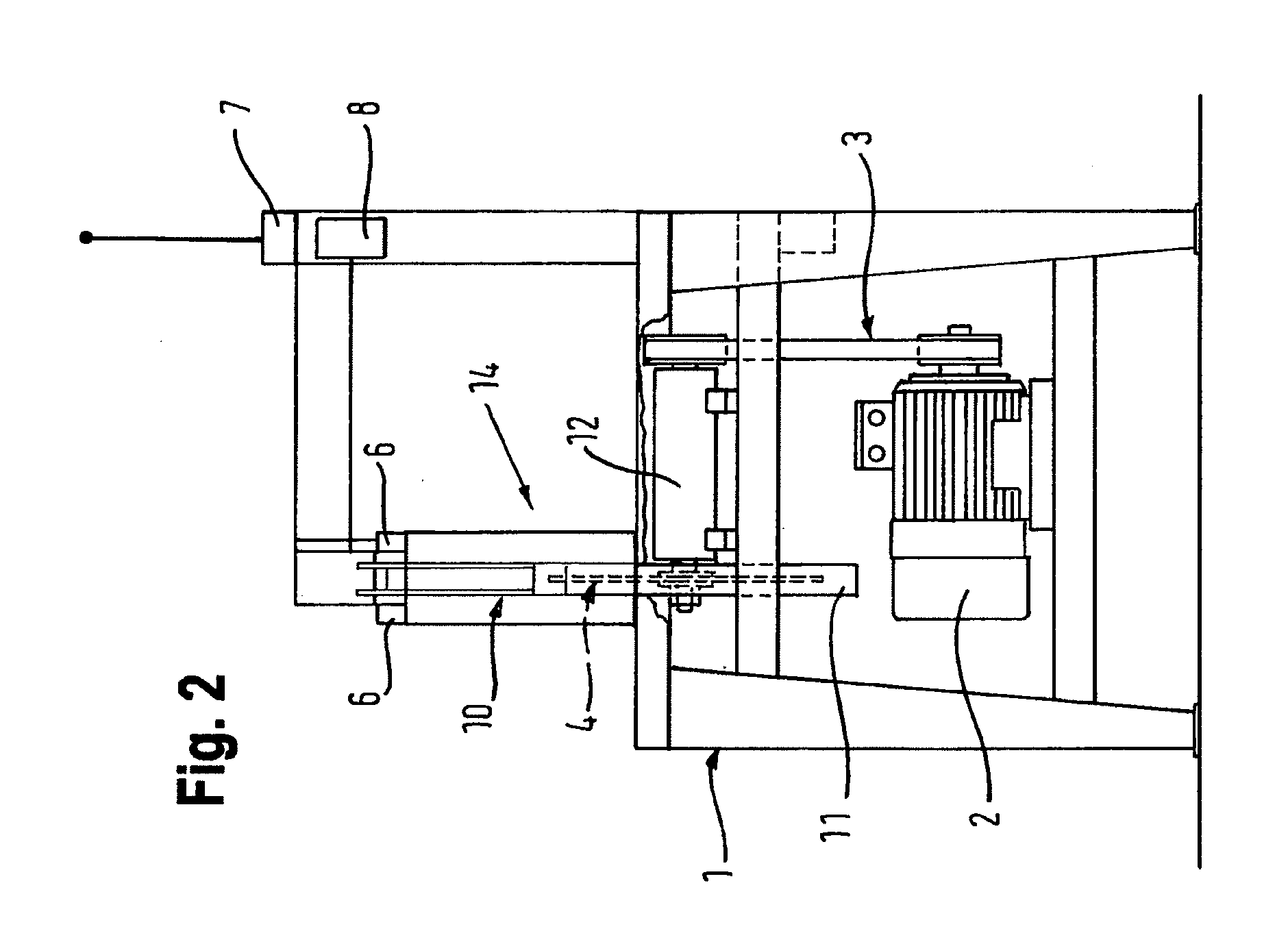
[0021]For example, the safety brake device according to the invention contains few or no parts subject to wear, so that hardly any maintenance work is required and maintenance costs are reduced accordingly.

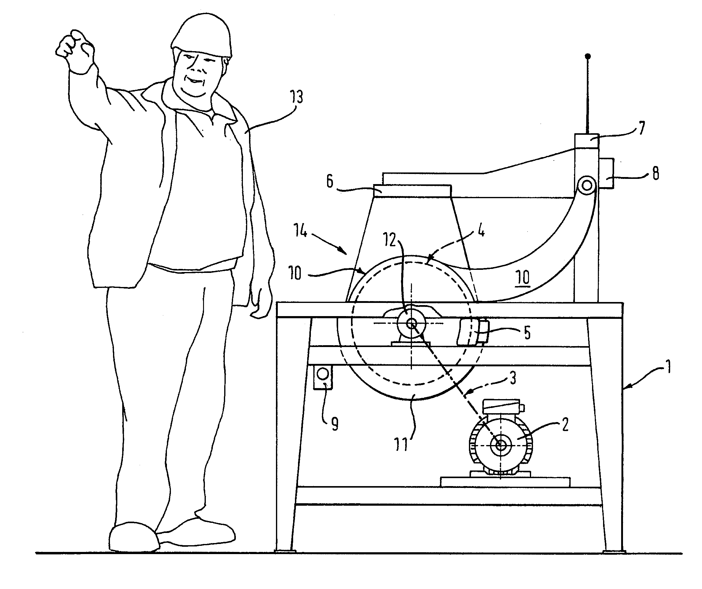
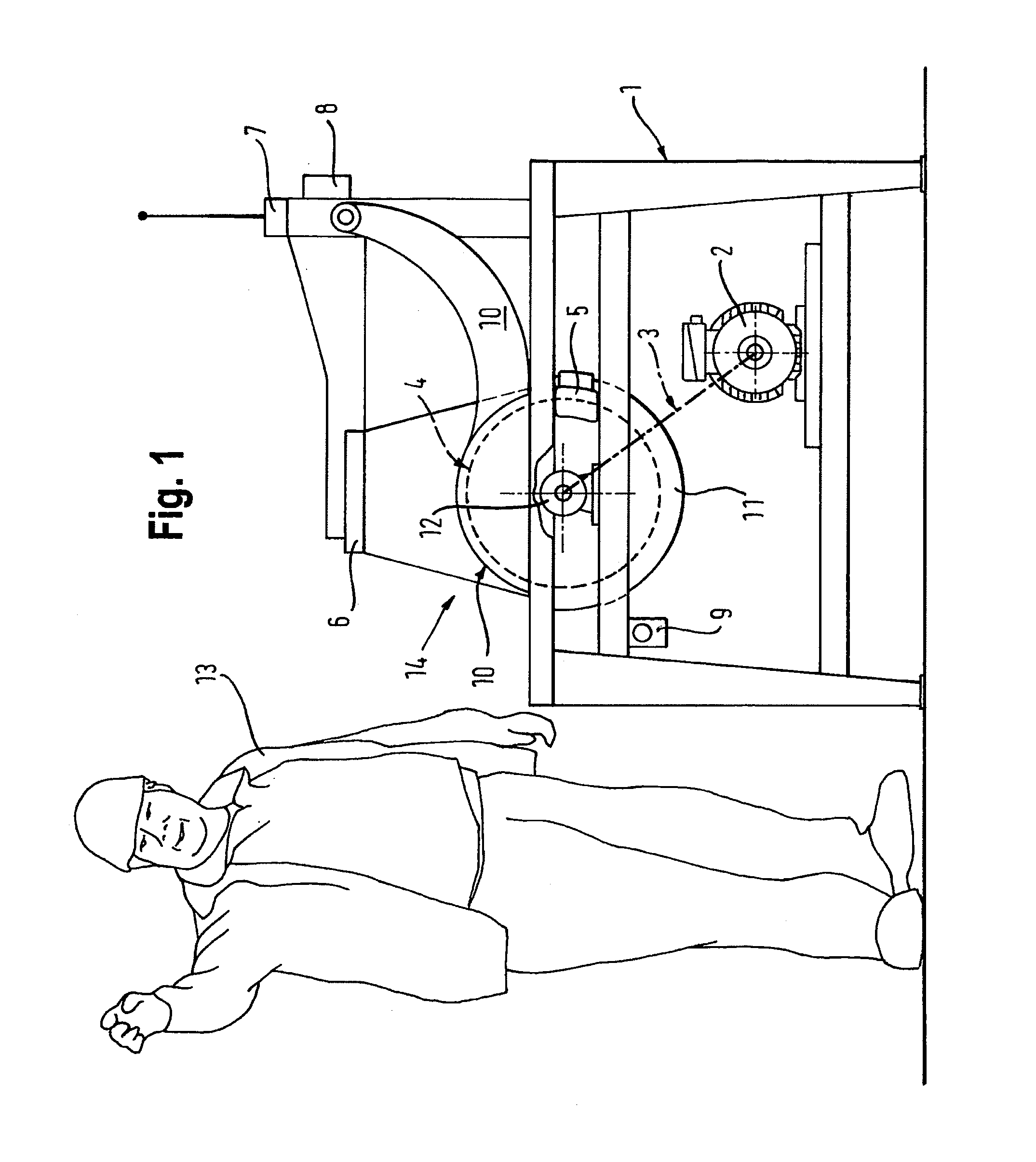
[0022]The invention also prevents a machine remaining in function when no operator is present in the working area. Finally, the operator's extremities are prevented from reaching the moving machine element, since this is stopped immediately through a brake device acting directly on the moving machine element. This makes it possible to reduce the stopping times of the moving machine elements to almost zero and thus prevent any injury to the operator.

[0023]Incidentally, th...


PUM


Abstract

A safety brake device for moving machine elements to prevent injury to the extremities of the operator of a machine if the distance of said operator from the moving machine element is less than a defined safety area. The device is characterized by an arrangement for detecting the operator position, in order to permit operation of the machine only if the operator remains within the defined working area, an arrangement for detecting the position of the extremities of the operator within a predefined safety zone, which enables the required work activities to be performed, and a brake device, by means of which the moving machine element can be immediately stopped if the extremities of the operator go beyond the safety area.

Description

BACKGROUND OF THE INVENTION[0001]1. Field of the Invention[0002]The invention relates to a safety brake device for moving machine elements designed to prevent injuries to the extremities of the operator of a machine[0003]2. Description of Related Art[0004]A number of safety devices are already known which are intended to reduce the danger of accidents to the operator from moving machine elements such as tools, blades, presses, or similar where the workpieces are fed or removed manually.[0005]These safety devices are in most cases very simple in design and do not offer full protection for the operator, since these only protect parts of the machine elements or tools, or the machine elements have a relatively long stopping time and it is thus still possible to reach into the hazardous area.[0006]Most of the safety devices currently known consist of separating mechanical safety covers which partially cover the hazardous areas, or emergency stop devices which cut off the energy supply an...

Claims


Application Information

Patent Timeline
Patent Type & Authority Applications(United States)
IPC IPC(8): F16P3/12F16D49/00B23Q11/00G05B19/42G05B19/4061
CPCB23Q11/0082B23Q11/0092G05B19/4061G05B9/02G05B19/0428F16P3/14F16P3/144
Inventor CALLIARI, UMBERTO
Owner CALLIARI UMBERTO
Why Eureka
Try Eureka