Deposition nozzle and apparatus for thin film deposition process

a technology of thin film and deposition nozzle, which is applied in the direction of lighting and heating apparatus, combustion types, coatings, etc., can solve the problems of large amount of precursor required, inability to completely remove the remaining precursor and by-products, and time-consuming extraction procedures

Active Publication Date: 2013-01-03
IND TECH RES INST
View PDF4 Cites 11 Cited by
  • Summary
  • Abstract
  • Description
  • Claims
  • Application Information

AI Technical Summary

Benefits of technology

[0009]The present disclosure provides a deposition nozzle and a deposition device which rapidly and uniformly acco...

Problems solved by technology

Although the technology disclosed in the prior art can achieve an object of mass production, not only the amount of required precursor is quite large but also the extraction procedure needs to spend a lot of time since the reaction chamber is usually quite large.
Another technique disclosed in the prior art exists a problem of not being capable of completely removing the remaining precursor and by-products.
Therefore, the spread of the precursor can not be blocked sufficiently such that the precursors sprayed...

Method used


Image

  • Deposition nozzle and apparatus for thin film deposition process
  • Deposition nozzle and apparatus for thin film deposition process
  • Deposition nozzle and apparatus for thin film deposition process

Examples


Embodiment Construction

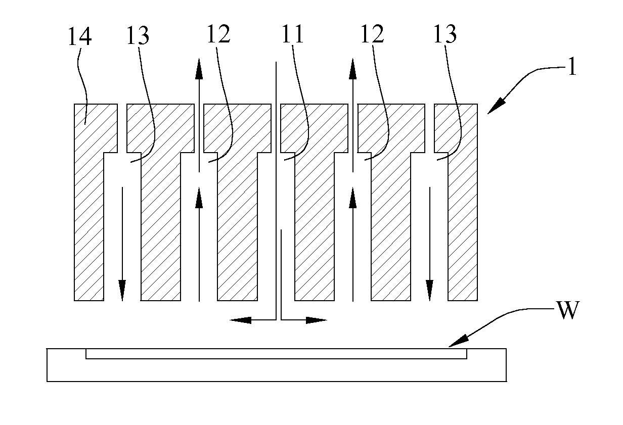
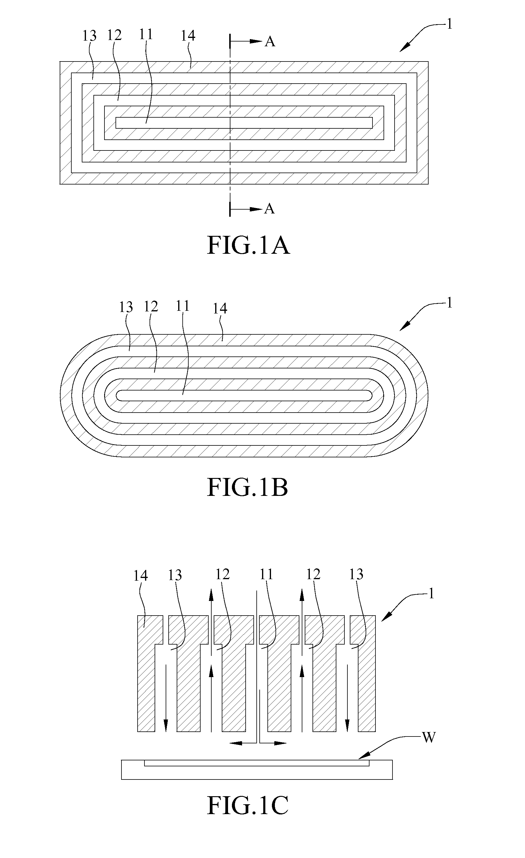
[0023]The structural description of a deposition nozzle according to the present disclosure are depicted with reference to FIGS. 1A-1C, wherein FIG. 1A is a schematically top view of the structure of the deposition nozzle 1 according to the present disclosure, FIG. 1B is another embodiment of the deposition nozzle 1 of FIG. 1A, and FIG. 1C is a schematically cross-sectional view taken along the line segment A-A.

[0024]The description herein is mentioned that, the deposition nozzle of the present disclosure can be applied in an atomic layer epitaxy process (ALE / ALD) so as to accomplish a deposition procedure on a substrate. Said substrate can be soft or hard, for instance, a glass substrate or a wafer of all kinds of shape.

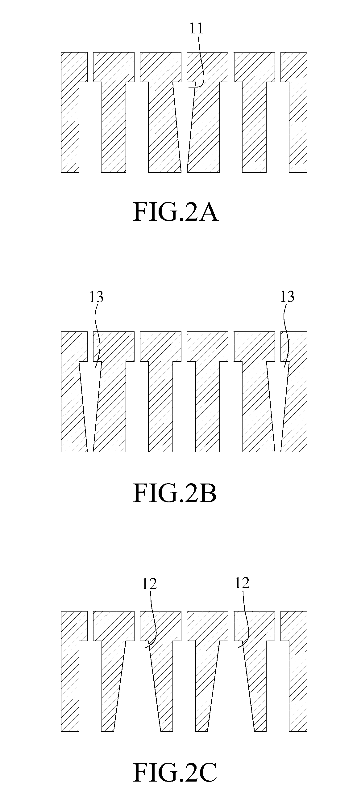
[0025]As illustrated, the deposition nozzle 1 includes a nozzle body 14, a precursor passageway 11, an extraction passageway 12, and an air curtain passageway 13.

[0026]The precursor passageway 11 is formed at a central region of the nozzle body 14, for a precursor g...


PUM

PropertyMeasurementUnit
Shapeaaaaaaaaaa
Frequencyaaaaaaaaaa

Abstract

A deposition nozzle and a deposition apparatus include a nozzle body, a precursor passageway formed at a central region of the nozzle body for a precursor gas to be sprayed on the substrate such that the precursor gas reacts with a surface of the substrate, an extraction passageway formed in the nozzle body and located at a peripheral side of the precursor passageway, and extracting residues after the precursor gas reacts with the surface of the substrate, and an air curtain passageway formed in the nozzle body and located at a peripheral side of the extraction passageway for isolating gas to be sprayed on the substrate so as to form a closed gas flow field enclosing a process reaction region between a substrate carrier and the deposition nozzle such that the residues after the precursor gas reacts with the surface of the substrate do not leak.

Description

CROSS-REFERENCE TO RELATED APPLICATIONS[0001]This application claims priority to Taiwanese Patent Application No. 100123273, filed on Jul. 1, 2011.BACKGROUND[0002]1. Technical Field[0003]The present disclosure relates to deposition nozzles and deposition apparatuses, and, more particularly, to a deposition nozzle which forms a closed gas flow field on a substrate between a substrate carrier and a deposition apparatus to which the deposition nozzle is applied.[0004]2. Description of Related Art[0005]The principle of atomic layer deposition technology is that process gas is rendered to perform chemical deposition reaction with a material surface so as to deposit a film with a thickness of atomic level on the material surface.[0006]Although the technology disclosed in the prior art can achieve an object of mass production, not only the amount of required precursor is quite large but also the extraction procedure needs to spend a lot of time since the reaction chamber is usually quite l...

Claims


Application Information

Patent Timeline
IPC IPC(8): C23C16/455B05B1/00C23C16/52
CPCC23C16/45551C23C16/482C23C16/4584C23C16/45574
Inventor HUANG, JEN-RONG
Owner IND TECH RES INST
Why Eureka
Try Eureka