Compact gantry for particle therapy

a particle therapy and compact technology, applied in the field of compact gantry, can solve the problems of large manufacturing cost of the gantry, inability to cover all treatment angles without moving the patient, and inability to cover all treatment angles

Active Publication Date: 2013-01-03
ION BEAM APPL
View PDF2 Cites 29 Cited by
  • Summary
  • Abstract
  • Description
  • Claims
  • Application Information

AI Technical Summary

Benefits of technology

[0020]More preferably, a beam line section between said gantry entrance point and an entrance of the first dipole magnet is a short drift section. This means that between the entrance point and the entrance of the first dipole magnet no quadrupole magnets are installed.
[0021]Even more preferably, the beam line section between said first and said second dipole magnet comprises five quadrupole magnets and the beam line section between said second and said third dipole magnet comprises no quadrupole magnet.
[0022]Even more preferably, the isocentric gantry is comprising means for rotating the gantry over an angular range of at least 180°.

Problems solved by technology

The drawback of this gantry is that it has large dimensions: a diameter of about 10 m and a length of more than 10 m. This gantry has also a large manufacturing cost.
The disadvantage of such an oblique gantry is that one can not cover all treatment angles without moving the patient.
Again the disadvantage of such an oblique gantry configuration is that not all treatment angles can be covered.
A disadvantage of such a gantry configuration is that a large spacing needs to be provided between the exit of the last bending magnet (in this example, the 135° magnet) and the gantry isocenter which results in a large gantry radius R. The scanning magnets need to be installed far enough from the isocenter (e.g. 2 m or more) in order to have a sufficiently large SAD (Source to Axis Distance).
A major disadvantage of this gantry configuration is that the last 90° bending magnet 16 needs to have a large gap (vertical) and a large pole width (horizontal) in order to be able to scan the beam over a large target area at isocenter (e.g. 25 cm×20 cm or 40 cm×30 cm).
As a consequence, the size and weight of such a 90° dipole magnet is large and moreover the power consumption is high.
A second disadvantage is that the straight parallel section between the second 60° dipole magnet and the last 90° bending magnet is relatively long which results in long axial gantry dimensions.

Method used


Image

  • Compact gantry for particle therapy
  • Compact gantry for particle therapy
  • Compact gantry for particle therapy

Examples


Embodiment Construction

[0033]The present invention will now be described in detail in relation to the appended drawings. However, it is evident that a person skilled in the art may conceive several equivalent embodiments or other ways of executing the present invention.

[0034]First, an exemplary single plane gantry comprising a pencil beam scanning system is disclosed, which is at the same time compact, has a reduced weight, has a reduced production cost and has a lower power consumption.

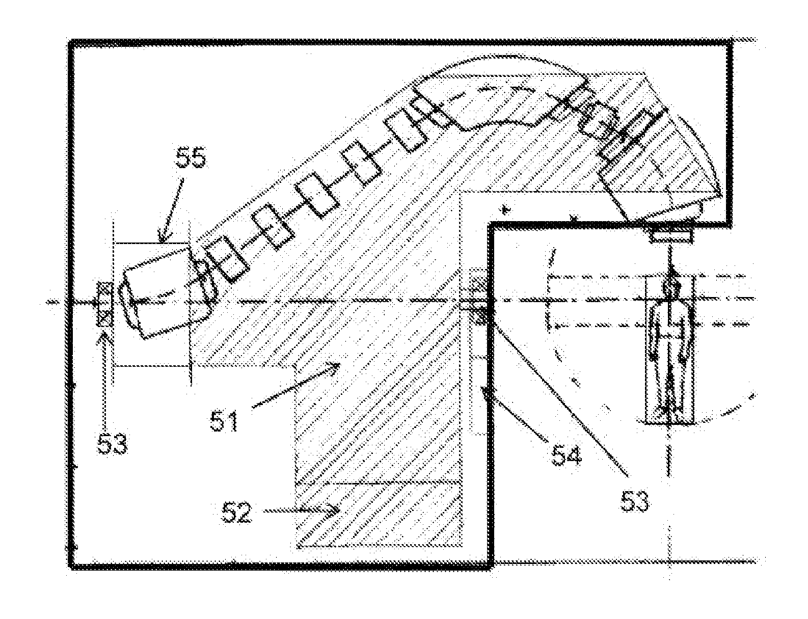
FIG. 2 shows a preferred layout of such a gantry. The gantry is represented in a 90° angular position (i.e. when looking in a direction parallel with the gantry axis, from isocenter 27 towards the first dipole magnet 20, the gantry is at three o'clock). The gantry has three dipole magnets 20, 21, 22 and has means 23 for scanning the beam in X and Y which are installed between the second dipole magnet 21 and the third dipole magnet 23. Between the first dipole magnet 20 and the second dipole magnet 21, a number of quadrupol...


PUM


Abstract

The present invention relates to a particle therapy apparatus used for radiation therapy. More particularly, this invention relates to a compact isocentric gantry for delivering particle beams perpendicularly to a rotation axis of the gantry. The gantry comprises three dipole magnets. The angle of the last dipole magnet is smaller than 90° and a most preferred bending angle for this last dipole magnet is 60°.

Description

FIELD OF THE INVENTION[0001]The present invention relates to a charged particle therapy apparatus used for radiation therapy. More particularly, this invention relates to a compact gantry for delivering particle beams.STATE OF THE ART[0002]Radiotherapy using charged particles (e.g. protons, carbon ions, . . . ) has proven to be a precise and conformal radiation therapy technique where a high dose to a target volume can be delivered while minimizing the dose to surrounding healthy tissues. A particle therapy apparatus comprises an accelerator producing energetic charged particles, a beam transport system for guiding the particle beam to one or more treatment rooms and, for each treatment room, a particle beam delivery system. One can distinguish between two types of beam delivery systems, fixed beam delivery systems delivering the beam to the target from a fixed irradiation direction and rotating beam delivery systems capable of delivering beam to the target from multiple irradiation...

Claims


Application Information

Patent Timeline
Patent Type & Authority Applications(United States)
IPC IPC(8): H01J3/14
CPCA61N5/01A61N5/10A61N5/1081H01J3/26G21K1/093A61N5/1077A61N2005/1087G21K5/04
Inventor JONGEN, YVES
Owner ION BEAM APPL
Why Eureka
Try Eureka