
Light Emitting Structure, Display Device Including a Light Emitting Structure and Method of Manufacturing a Display Device Including a Light Emitting Structure

a technology of light-emitting structures and display devices, which is applied in the direction of thermoelectric device junction materials, semiconductor devices, electrical apparatus, etc., can solve the problems of low functional stability of organic layers, low purity of light-emitting colors, and conventional organic light-emitting displays. achieve enhanced color reproducibility, improve color purity, and improve brightness

Active Publication Date: 2013-01-03
SAMSUNG DISPLAY CO LTD
View PDF5 Cites 31 Cited by
  • Summary
  • Abstract
  • Description
  • Claims
  • Application Information

AI Technical Summary

Benefits of technology

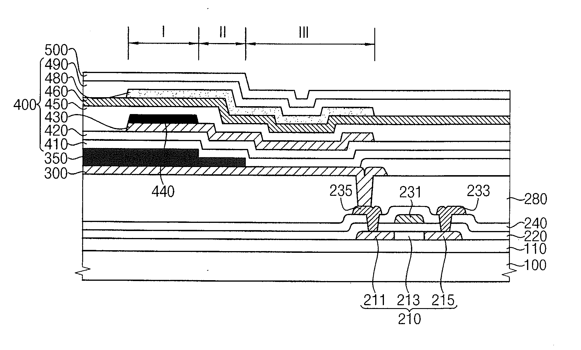
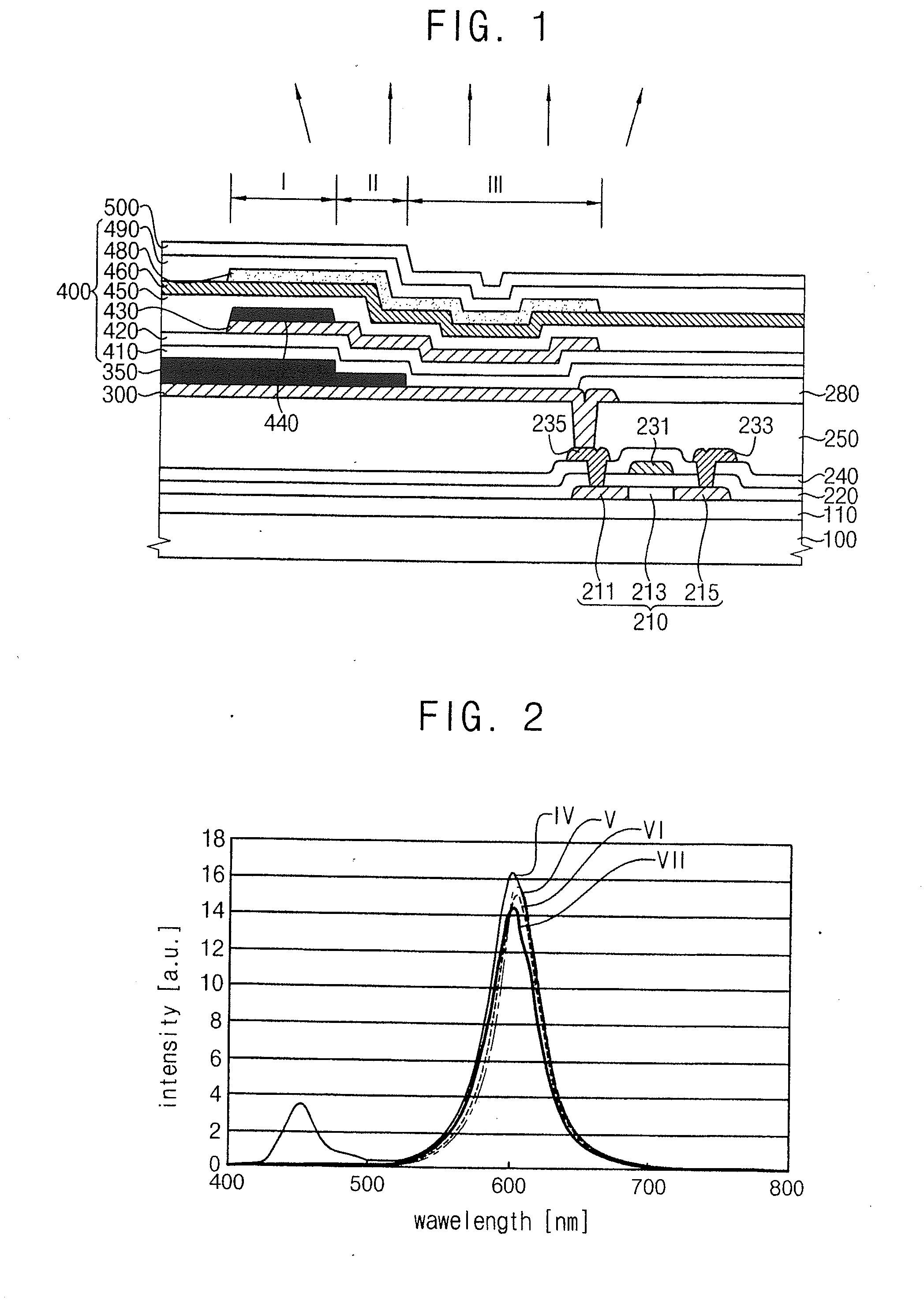
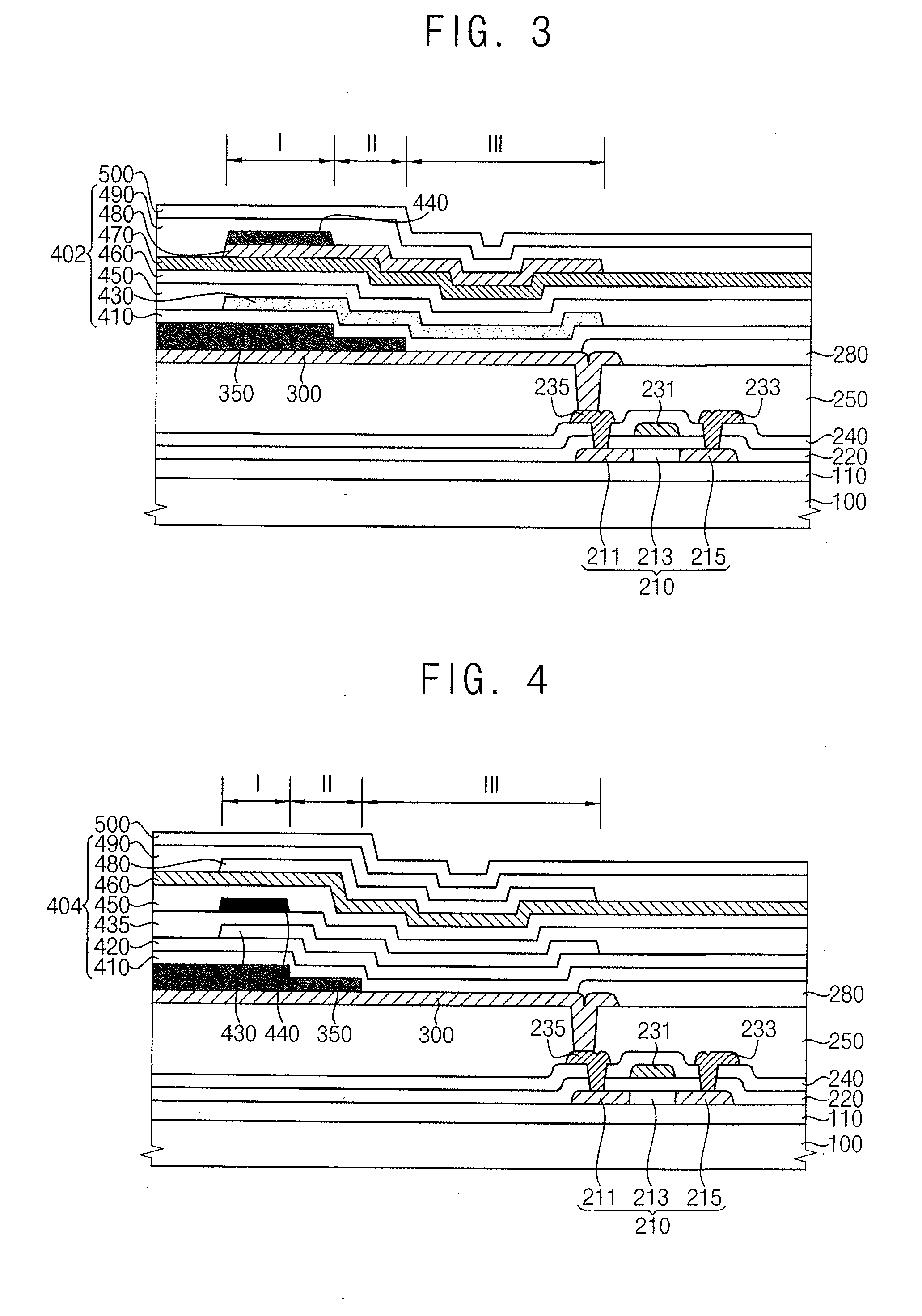
The present invention is directed toward a light emitting structure with improved color purity, enhanced color reproducibility, and increased brightness. It also relates to a display device capable of displaying high resolution images with improved color purity and enhanced brightness. Additionally, it is directed toward a method of manufacturing such a display device. The invention improves the color purity, brightness, and color gamut of the display device by designing each sub pixel region with different optical resonance distances, which allows lights of different wavelengths to be emitted from each region. This eliminates the need for additional layers such as a color filter, reduces manufacturing costs, and simplifies the manufacturing process. Furthermore, the separation of the blue light emitting layer from the red and green layers improves color stability and extends the lifetime of the blue light emitting layer. The display device can display high resolution images with high color purity and high brightness without a color filter.

Problems solved by technology

However, the conventional organic light emitting display may have some disadvantages such as relatively low functional stability of the organic layers and low purity of colors of light.
Even though a color filter may be disposed over the organic layers to improve the purity of colors of light, manufacturing processes may be complicated and also manufacturing cost for the display device may be increased.
Further, the conventional organic light emitting display device may have low luminance efficiency because of the color filter.

Method used


Image

  • Light Emitting Structure, Display Device Including a Light Emitting Structure and Method of Manufacturing a Display Device Including a Light Emitting Structure
  • Light Emitting Structure, Display Device Including a Light Emitting Structure and Method of Manufacturing a Display Device Including a Light Emitting Structure
  • Light Emitting Structure, Display Device Including a Light Emitting Structure and Method of Manufacturing a Display Device Including a Light Emitting Structure

Examples


Embodiment Construction

[0075]Various example embodiments will be described more fully hereinafter with reference to the accompanying drawings, in which some example embodiments are shown. The present invention may, however, be embodied in many different forms and should not be construed as limited to the example embodiments set forth herein. Rather, these example embodiments are provided so that this description will be thorough and complete, and will fully convey the scope of the invention to those skilled in the art. In the drawings, the sizes and relative sizes of layers and regions may be exaggerated for clarity.

[0076]It will be understood that when an element or layer is referred to as being “on,”“connected to,” or “coupled to” another element or layer, it can be directly on, connected, or coupled to the other element or layer, or one or more intervening elements or layers may be present. When an element is referred to as being “directly on,”“directly connected to,” or “directly coupled to” another e...


PUM


Abstract

A light emitting structure includes a first hole injection layer, a first organic light emitting layer, a charge generation layer, a second hole injection layer, a second organic light emitting layer, an electron transfer layer, and a blocking member. The light emitting structure has first, second, and third sub-pixel regions. The first organic light emitting layer may be on the first hole injection layer. The charge generation layer may be on the first organic light emitting layer. The second hole injection layer may be on the charge generation layer. The second organic light emitting layer may be on the second hole injection layer. The electron transfer layer may be on the second organic light emitting layer. The blocking member may be at at least one of the first to the third sub-pixel regions.

Description

CROSS-REFERENCE TO RELATED APPLICATION[0001]This application claims priority under 35 U.S.C. §119 to Korean patent Application No. 10-2011-0063644, filed on Jun. 29, 2011, the disclosure of which is hereby incorporated by reference herein in its entirety.BACKGROUND[0002]1. Field[0003]Example embodiments of the present invention relate to a light emitting structure, a display device including a light emitting structure, and a method of manufacturing a display device including a light emitting structure.[0004]2. Description of Related Art[0005]An organic light emitting display (OLED) device displays information such as images and characters using light generated from an organic layer therein. As for the organic light emitting display device, light may be generated by combination of holes from an anode and electrons from a cathode occurred at the organic layer between the anode and the cathode. In various display devices such as a liquid crystal display (LCD) device, a plasma display (...

Claims


Application Information

Patent Timeline
Patent Type & Authority Applications(United States)
IPC IPC(8): H01L33/44H01L33/36
CPCH01L27/3211H01L51/5265H01L51/5096H01L51/504H10K59/35H10K50/13H10K59/876H10K71/18H10K71/00H10K50/181H10K50/852H10K59/126H10K50/18H10K59/1201
Inventor LEE, SUNG-SOOSONG, OK-KEUNKIM, SE-IL
Owner SAMSUNG DISPLAY CO LTD
Learn More