
Lamp failure detector

Inactive Publication Date: 2013-01-03
APPLIED MATERIALS INC
View PDF4 Cites 8 Cited by
  • Summary
  • Abstract
  • Description
  • Claims
  • Application Information

AI Technical Summary

Benefits of technology

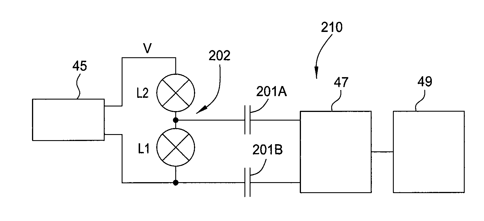
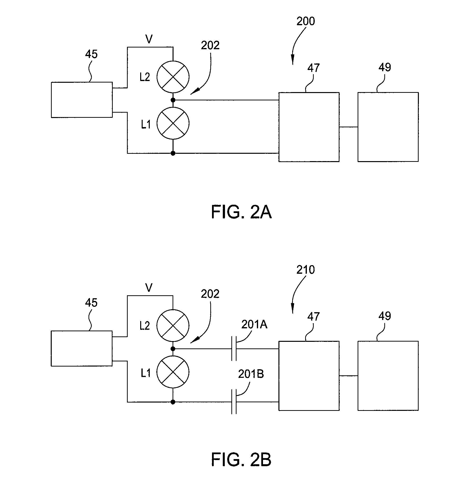
The present invention relates to apparatus and methods for detecting lamp failure in a rapid thermal processing (RTP) tool. One embodiment involves a lamp failure detector that includes a voltage data acquisition module positioned to sample voltage signals on a circuit path formed by at least two serially connected lamps of the plurality of lamps. A first capacitor and a second capacitor are coupled to the circuit path at nodes associated with a first lamp and a second lamp of the at least two serially connected lamps, respectively. The controller is adapted to receive digital values of the sampled voltage signals from the voltage data acquisition module and determine the status of one or more lamps based on a voltage drop across the first lamp of the at least two serially connected lamps. Another embodiment involves a relation between the voltage drop across the first lamp and the total voltage drop of the circuit path. A method involves sampling voltage signals along a circuit path formed by at least two serially connected lamps, determining the voltage drop across the first lamp, and identifying lamp failure based on the relationship between the voltage drop across the first lamp and the total voltage drop of the circuit path. This invention provides a more efficient way to detect lamp failure in RTP tools, improving efficiency and accuracy.

Problems solved by technology

A result of the short heating cycle used in RTP is that any temperature gradients that may exist across the wafer surface can adversely affect wafer processing.
However, current approaches will not usually produce the temperature uniformity needed.
Variation in heat intensity due to element failure or poor performance can greatly compromise the desired temperature profile control and result in unacceptable process results.

Method used


Image

  • Lamp failure detector
  • Lamp failure detector
  • Lamp failure detector

Examples


Embodiment Construction

[0019]Embodiments of the present invention generally relate to apparatus and methods for detecting lamp failure, and more specifically for detecting lamp failure of serially connected lamps in a rapid thermal processing (RTP) tool.

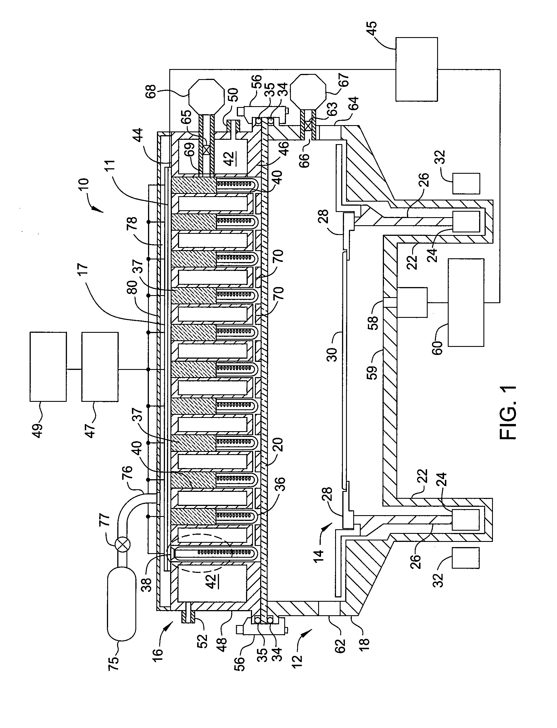
[0020]FIG. 1 illustrates a partial cross-section of a semiconductor processing system 10 according to one embodiment. The semiconductor processing system 10 may generally include a semiconductor processing chamber 12, a wafer handling or support apparatus 14 located within the semiconductor processing chamber 12, and a lamphead or heat source assembly 16 located on the semiconductor processing chamber.

[0021]The semiconductor processing chamber 12 includes a main body 18 and a window 20 resting on an upper edge of the main body 18. An o-ring 34 is located between the window 20 and the main body 18 to provide an air-tight seal at the interface. The window 20 may be made of a material that is transparent to infrared light. For example, the window 20 may be ma...


PUM


Abstract

Apparatus and methods for detecting lamp failure in a rapid thermal processing (RTP) tool are provided. Lamp failure detection systems are provided that can accommodate DC and / or AC voltages. The systems sample voltage signals along a circuit path formed by at least two serially connected lamps, calculate a voltage drop across the first lamp of the at least two serially connected lamps based on the sampled voltage signals, and determine whether a lamp failure has occurred based on a relationship between the voltage drop across the first lamp and a total voltage applied to the circuit path.

Description

BACKGROUND OF THE INVENTION[0001]1. Field of the Invention[0002]Embodiments of the present invention generally relate to apparatus and methods for detecting lamp failure, and more specifically for detecting lamp failure of serially connected lamps in a rapid thermal processing (RTP) tool.[0003]2. Description of the Related Art[0004]Rapid thermal processing (RTP) is any thermal processing technique that allows rapid heating and rapid cooling of a substrate such as a silicon wafer. The specific peak temperature and heating time used depend on the type of wafer processing. RTP wafer processing applications include annealing, dopant activation, rapid thermal oxidation, and silicidation among others. The rapid heating to relatively high temperatures followed by the rapid cooling that characterize RTP provides more precise wafer processing control. The trend for thinner oxides used in MOS gates has led to requirements of oxide thicknesses less than 100 Angstroms for some device applicatio...

Claims


Application Information

Patent Timeline
IPC IPC(8): H05B37/03
CPCH05B37/036H05B37/038H01L21/324H01L22/10H01L22/14H05B47/235H05B47/23
Inventor SEREBRYANOV, OLEGGOLDIN, ALEXANDER
Owner APPLIED MATERIALS INC
Learn More