Plasma display device driving method, plasma display device, and plasma display system

a technology of plasma display device and driving method, which is applied in the direction of television system, instruments, computing, etc., can solve the problems of disadvantage and difficult 3d vision, and achieve the effect of reducing crosstalk and improving image display quality

Inactive Publication Date: 2013-01-03
PANASONIC CORP
View PDF6 Cites 8 Cited by
  • Summary
  • Abstract
  • Description
  • Claims
  • Application Information

AI Technical Summary

Benefits of technology

[0046]Thus, the plasma display apparatus usable as a 3D image display apparatus can reduce the crosstalk for a user who views the 3D image displayed on the panel through the shutter glasses, and can improve the image display quality.

Problems solved by technology

When the crosstalk occurs, the 3D vision becomes difficult, disadvantageously.

Method used


Image

  • Plasma display device driving method, plasma display device, and plasma display system
  • Plasma display device driving method, plasma display device, and plasma display system
  • Plasma display device driving method, plasma display device, and plasma display system

Examples


first exemplary embodiment

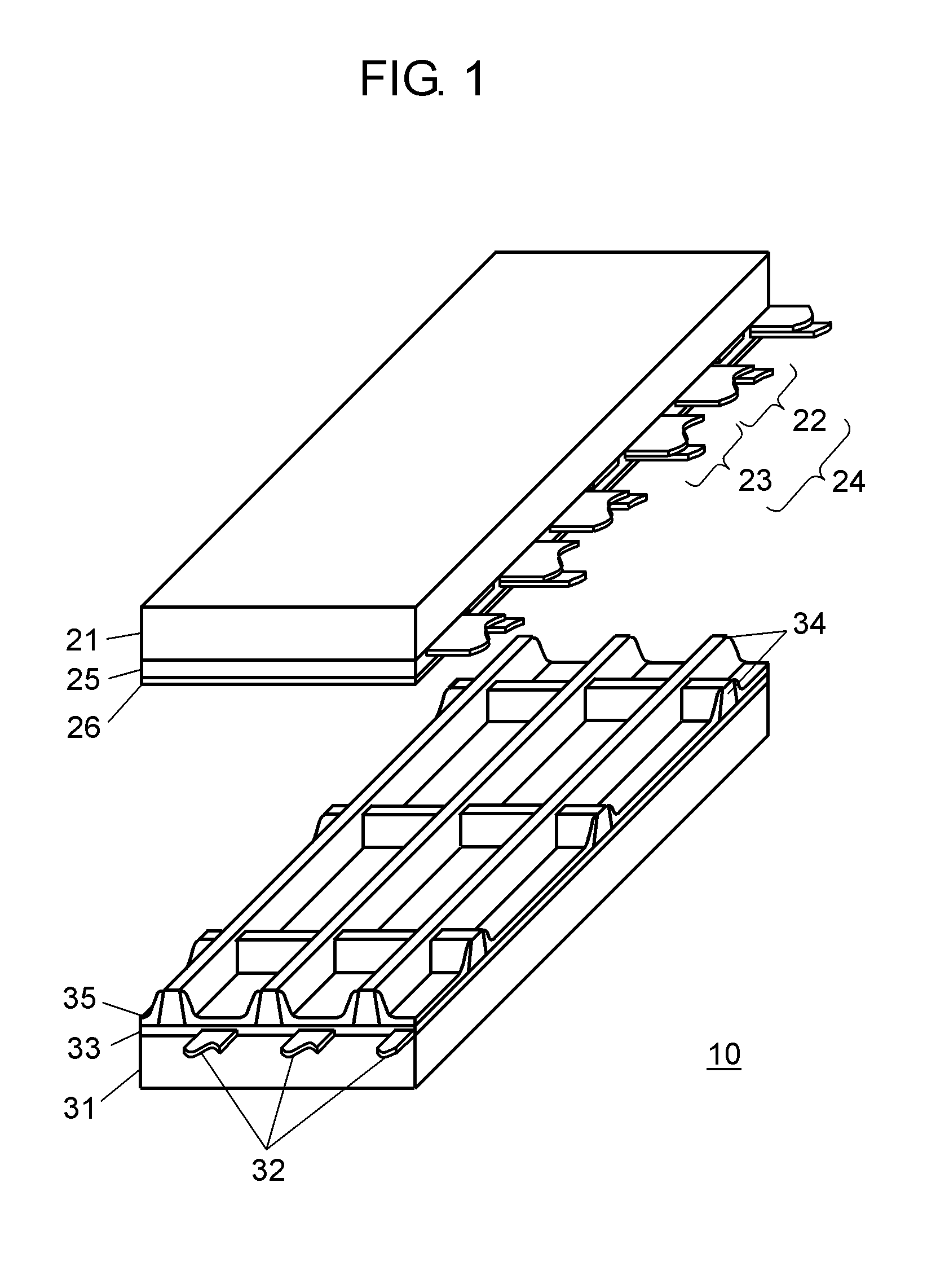
[0072]FIG. 1 is an exploded perspective view showing the structure of panel 10 used in a plasma display apparatus in accordance with a first exemplary embodiment of the present invention. A plurality of display electrode pairs 24 formed of scan electrodes 22 and sustain electrodes 23 is disposed on glass-made front substrate 21. Dielectric layer 25 is formed so as to cover scan electrodes 22 and sustain electrodes 23, and protective layer 26 is formed on dielectric layer 25.

[0073]Protective layer 26 is made of a material mainly made of magnesium oxide (MgO) in order to reduce the discharge start voltage in a discharge cell. The magnesium oxide has been used as a material of a panel, and has a large secondary electron emission coefficient and high durability when neon (Ne) gas and xenon (Xe) gas are filled.

[0074]A plurality of data electrodes 32 is formed on rear substrate 31, dielectric layer 33 is formed so as to cover data electrodes 32, and mesh barrier ribs 34 are formed on diel...

second exemplary embodiment

[0237]In the first exemplary embodiment, crosstalk is suppressed by adding predetermined gradation value K to an image signal (luminance signal) corresponding to one field period in the field in which the number of pixels where an afterimage is expected to occur is equal to or larger than number-of-pixels threshold Na. In the present invention, the method of suppressing crosstalk is not limited to this method.

[0238]For example, an image display region of panel 10 is divided into a plurality of display blocks, and the number of pixels where an afterimage is expected to occur is counted in each display block. In a display block having a large counting result, the crosstalk can be suppressed by adding predetermined gradation value K to the image signal (luminance signal) and increasing the luminance in the field. In the second exemplary embodiment, one example of such structure is described.

[0239]FIG. 8A and FIG. 8B are diagrams for schematically showing an example where panel 10 is di...


PUM


Abstract

A plasma display apparatus usable as a 3D image display apparatus can reduce the crosstalk for a user who views a 3D image displayed on a plasma display panel through shutter glasses. For this purpose, the plasma display apparatus displays the 3D image on the plasma display panel having a plurality of pixels each of which is formed of a plurality of discharge cells by alternately repeating a right-eye field and a left-eye field. The plasma display apparatus adds a predetermined gradation value to an image signal to be displayed in a certain field when the number of pixels where the gradation equal to or higher than a high gradation threshold is displayed in the field immediately before a certain field and the gradation equal to or lower than a low gradation threshold is displayed in the certain field is equal to or larger than a number-of-pixels threshold.

Description

TECHNICAL FIELD[0001]The present invention relates to a driving method of a plasma display apparatus, a plasma display apparatus, and a plasma display system that alternately display, on a plasma display panel, a left-eye image and a right-eye image capable of being three-dimensionally viewed using shutter glasses.BACKGROUND ART[0002]An alternating-current surface discharge type panel typical as a plasma display panel (hereinafter referred to as “panel”) has many discharge cells between a front substrate and a rear substrate that are faced to each other. The front substrate has the following elements:[0003]a plurality of display electrode pairs disposed in parallel on a front glass substrate; and[0004]a dielectric layer and a protective layer for covering the display electrode pairs.Here, each display electrode pair is formed of a pair of scan electrode and sustain electrode.[0005]The rear substrate has the following elements:[0006]a plurality of data electrodes disposed in parallel...

Claims


Application Information

Patent Timeline
Patent Type & Authority Applications(United States)
IPC IPC(8): G09G3/28G09G3/288G09G3/292G09G3/296G09G3/298
CPCG09G3/003G09G2320/0233G09G2320/0257G09G2360/16G09G3/2927H04N13/0438G09G2320/0238G09G2320/0271G09G2340/16H04N5/70H04N13/341G09G3/28H01J11/20
Inventor ORIGUCHI, TAKAHIKOSHIOZAKI, YUYAKIGO, SHIGEOYOSHIHAMA, YUTAKAISHIZUKA, MITSUHIRO
Owner PANASONIC CORP
Why Eureka
Try Eureka